
|
Page 2 The project begins |
|
|
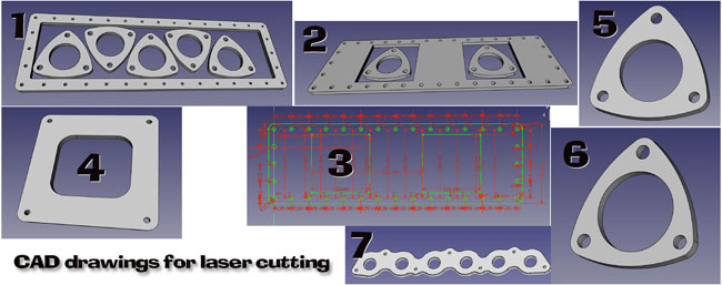
I had to learn how to draw in CAD to make all the flanges needed for getting the engine to run. Since the intake was missing, I had to design my own.
1. Upper intake flange ( with a bunch of 2" exhaust flanges to save material).
|
|
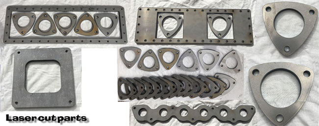
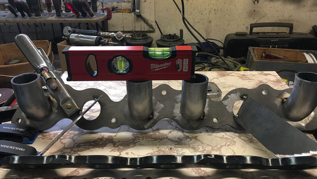
A call came from the laser cutting company. The parts I had drawn and ordered were cut and ready for delivery. I tried to lay out the parts like in the previous pic. Plans call for a modular exhaust, so that parts of it can be easily changed, say, to a different type of muffler with just unbolting 6 bolts, hence the wealth of triangular shaped flanges.
The bigger 2-1/2" ones will be used as header collectors, and also on other projects.
|
|
|
|
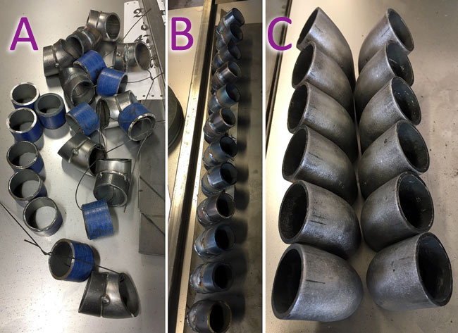
All parts ( tube bends and sheet metal) had mill scale removed with acid, as discussed later. Work on the intake runners started with cutting short pieces of straight tubing with a 13 degree angle, then a 37 degree angle of a pipe bend. Of course doing this cutting free hand with an angle grinder using a simple jig, the result is not very accurate. A. After cutting and adjusting, the pieces were paired and tacked together. B. Lastly they were again paired with a third part and welded to make 12 equal length runners. C. All 24 welds were ground off, and the insides were smoothed with a small grinder with a rotating file. |
|
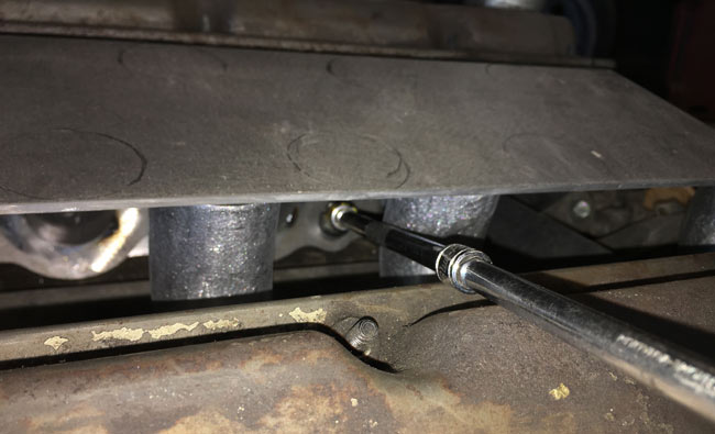
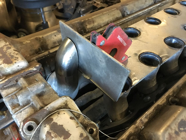
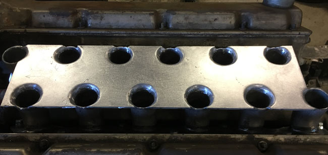
Checking for clearance for the intake bolts under the plenum floor. This will work, but the intake will be very tall. |
|
|
|
The intake off the engine to tack the intake runners to the flanges.
|
|
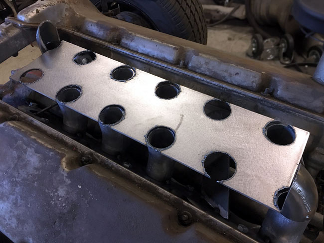
When eight runners were tacked to the intake flanges, it was all bolted back to the heads. After some measuring and planning, a plywood template was cut with a hole saw, and it was used to cut the holes for the intake runners in the plenum floor piece.
After this the rest of the runners were tacked to the flanges, making sure they fit the already cut holes in the plenum floor.
|
|
|
|
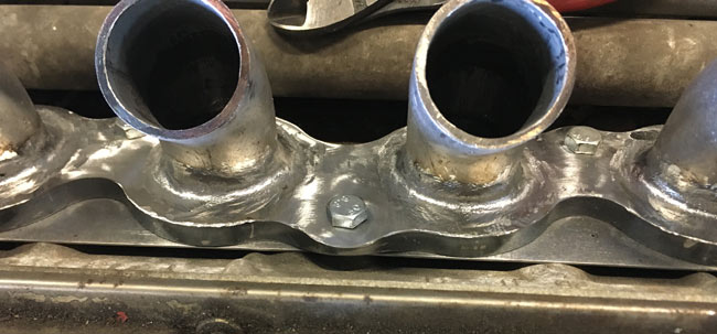
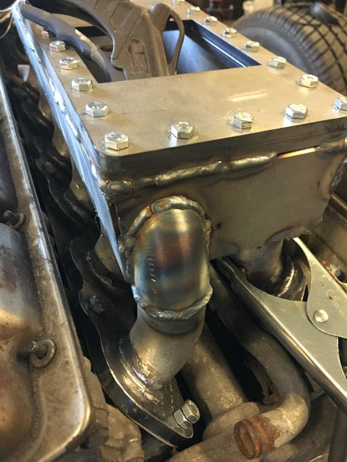
The plenum is designed short, and the outermost runners will turn into the ends of the plenum by using tube bends cut to fit to the plenum end walls. The holes in the plenum floor will be ground to fit loosely around the runnes, and the conjunctions will be ground round and smooth to facilitate air flow. |
|
After welding the intake runners to the flanges, the welds were ground. |
|
|
|
The plenum floor was then welded to the intake runners, and the edges where the runners meet the plenum floor were ground to a rounded shape. |
|
The parts for the plemum itself were cut to exact sizes, and the whole plenum was assembled and welded. |
|
|
|
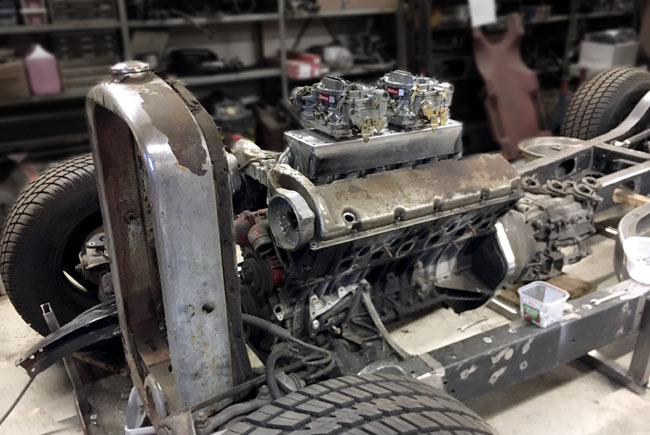
Finally we can see what the intake looks like with carbs and all. It's high and suitably impressive looking, but will probably just fit under the hood. |
|
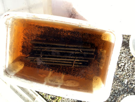
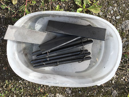
Mill scale is very hard to get ground off hot rolled steel. Etching it off with mild acids works.
This works amazingly well but is a bit smelly, so it's better done outside. Also, acid in the shop may make metal parts in the shop flash rust quickly. |
 |
 |
 |
|
Four hours has passed, and all the mill scale sits on the bottom of the container |
The parts are rinsed with water, and then washed in a weak soda solution to neutraize the acid, then dried. |
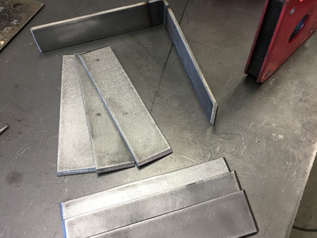
After the acid dip, the mill scale is gone, and the parts can be sanded smooth with just sandpaper. |