|
Page 2 The project begins |
|
The rear part of the frame, under which the fuel tank has been mounted, was cut off. Plans are to mount it a few inches lower, and also to extend the bodywork downwards the same amount to make for a better look. There's also a possibility the rear part of the frame never comes back.
|
|
|
|
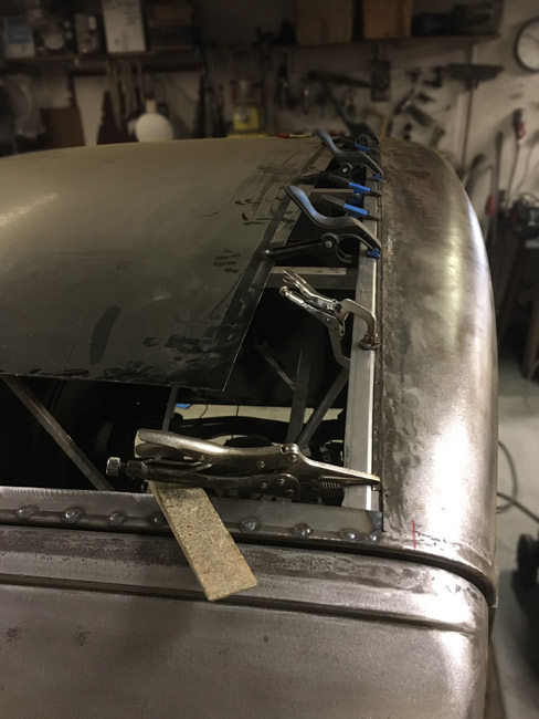
The roof will be glued on with body panel adhesive. Since the roof is a bit too narrow, in that the outermost edges bend down a bit too much, the roof has to be cut down smaller than ideal for gluing. To ensure theat the area for bonding is big enough, 1-1/2" strips of sheetmetal is welded to the roof sides.
|
|
Most of the sheet metal strips have been tacked to the roof sides. |
|
|
|
When done, there is a distinct location for the new roof to lay down into. |
|
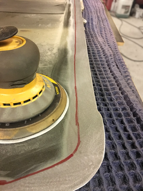
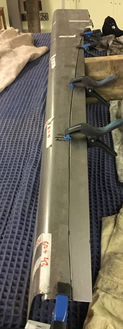
The roof sheet laid down upside down on a makeshift table. It's cut down to size, and the primer and paint is ground off to make the whole thing ready for test fitting and adhesive. |
|
|
|
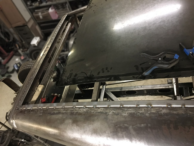
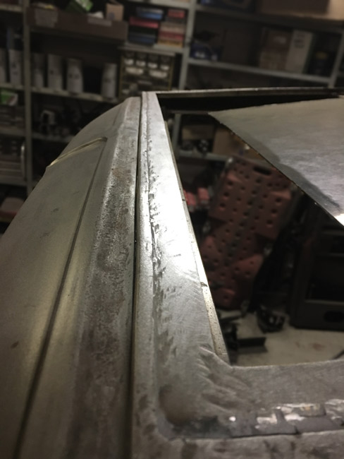
The roof sheet was lifted back onto the body, and some small adjustments were done. Now that it fits nicely it's nothing short of amazing, how well the shape and crown of the Volvo V70 roof works on the Buick. The strips that were welded in earlier, were adjusted by hammering and bending, until they follow the crown of the roof, so there's less than 40 thou (1mm)of space for the glue all around. |
|
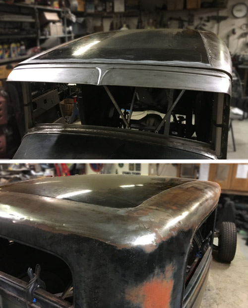
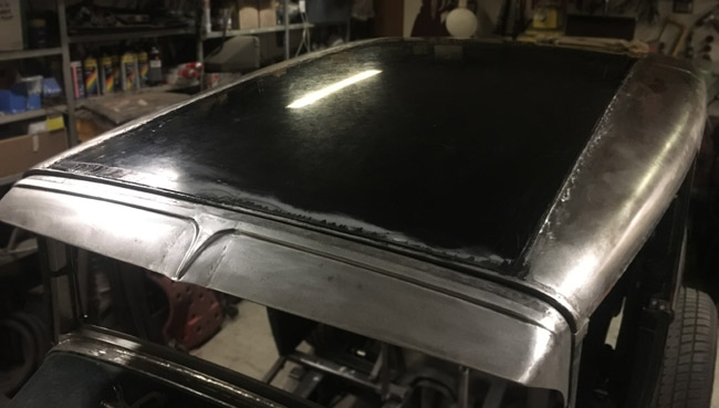
The roof glued to the body with 2K body panel adhesive. |
|
|
|
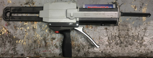
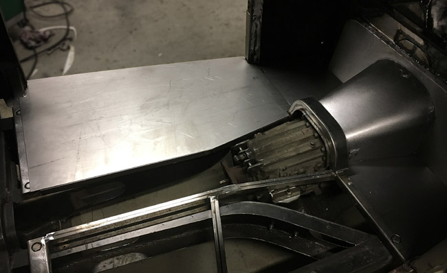
This is the glue gun that was used. It features a blending nozzle, that presses the two components back and forth into eachother multiple times, before it coming out in a ready to use bead. |
|
Time to turn to the aprons, since it's much easier to work on them now, before the floor panels go in.
|
|
|
|
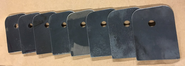
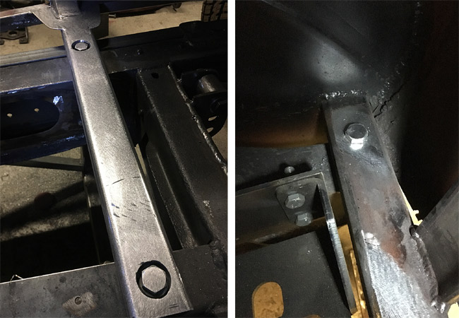
After figuring out how to attach the aprons to the frame, eight mounts were designed, cut and drilled from 1/8" thick´sheetmetal.
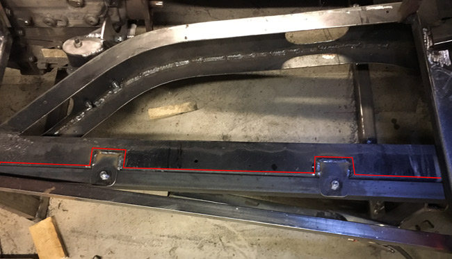
Two 2 meter long sticks of 1-3/16" angle iron were acquired and cut to
length. Holes were drilled and then the new parts were bolted together. |

|
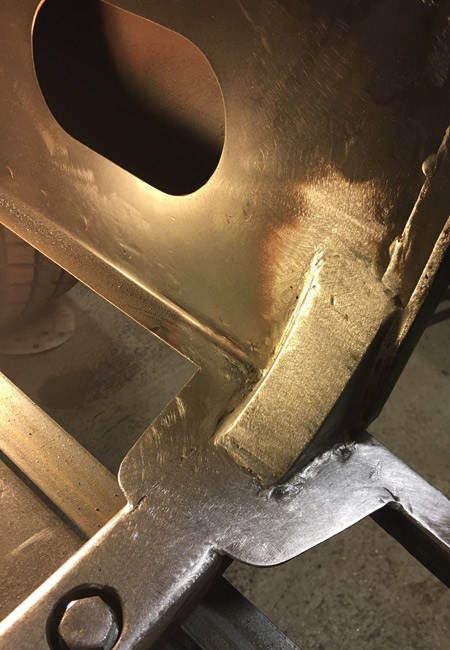
The assembly was then held in place, and the apron mounts welded to the top of the frame, as outlined in red here. |
|
|
|
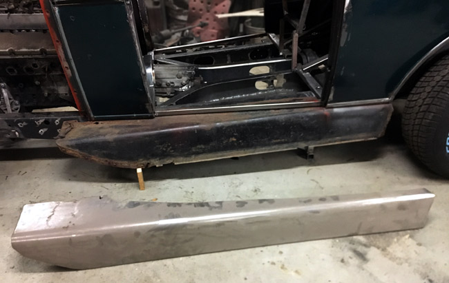
The top side of the driver's side apron was a bit too narrow, and as a result it has to be widened a bit to fit. Luckily this widening won't show as it will be hidden under the body, so it's pretty easy work. The new strip is clamped on here, and it just has to be welded before being mated to its mounts on the frame. The angle iron is going to keep the flimsy edge of the apron straight. |
|
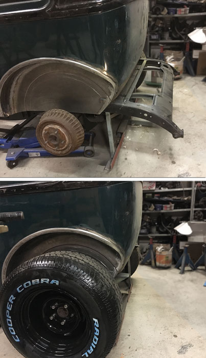
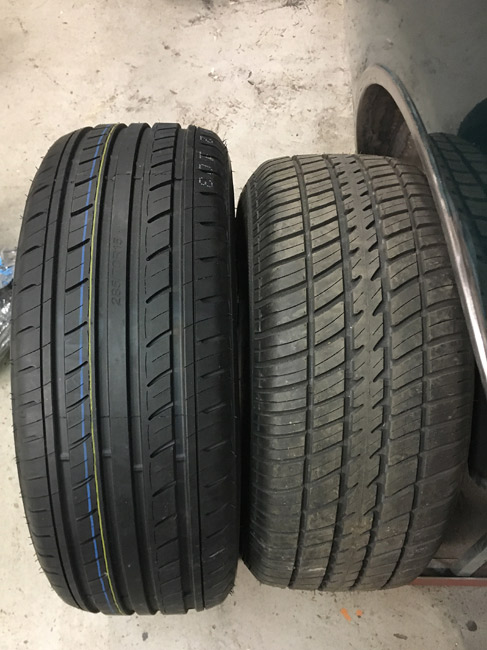
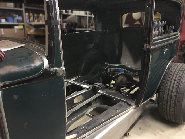
The Cooper Cobra 275/60-15" looked too small from the get go, and even as the plan was to use widened steelies, the chance to buy four good looking slot mags was jumped upon. New, bigger tires were ordered for the new rims. and here's a comparison. The new ones are significantly bigger. (285/70-15") (November 2022) |
|
|
|
|
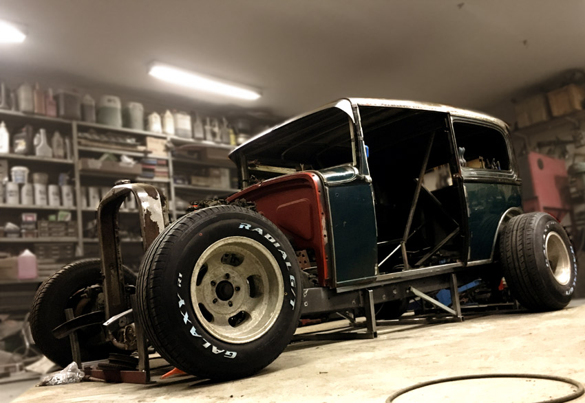
The look is more aggressive now, and as the tires are bigger, the whole car looks more compact.
|
|
|
The B-pillars got small gussets against he floor. The little shelf around the gusset is there for the floor to weld to. |
|
|
|
Four more body mounts were made, so now the bracing could be cut out of the body.
|
|
The lower cowl area is rusty, and also one of the last places where rust repairs are still pending.
|
|
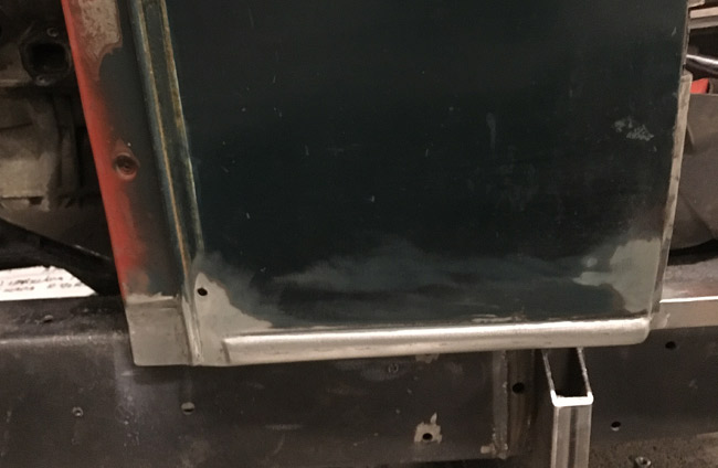
After some grinding, this side is done. |
|
|
The right hand side was a bit worse, so a bigger patch panel had to be made.
|
|
|
|
Then the fold was bent back, and then bent back more, over a piece of tubing. |
|
Then another bend was bent on the sheet metal brake. The final bend couldnt be done on the machine, so it had to be hammered to 90 degrees.
|
|
|
|
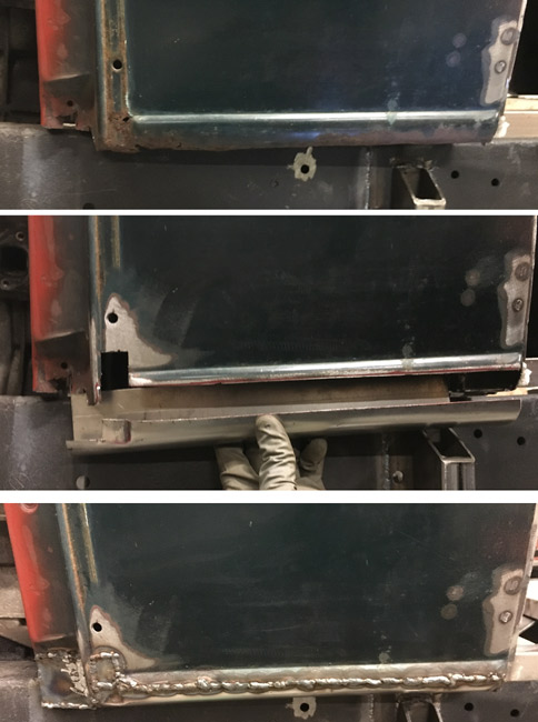
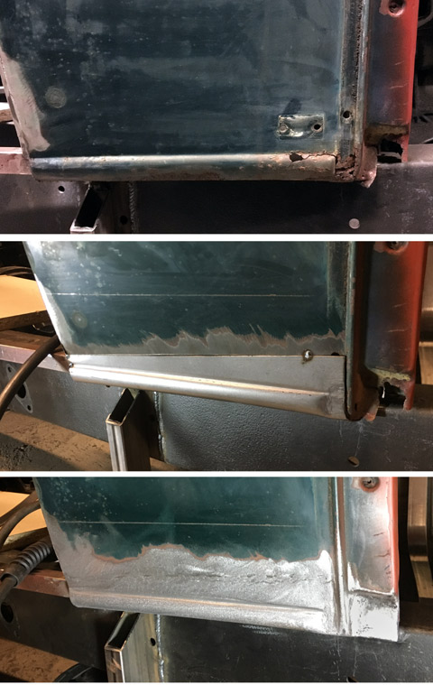
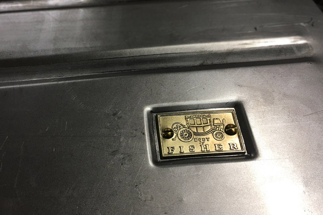
Here's how the patch itself was welded in. The top pic shows the rusty bottom of the cowl, and you can see where the little square brass "Body by Fisher" plaque has been screwed to the cowl. in the middle pic, the new panel is tacked to the cowl In th bottom pic the welds have been ground. |
|
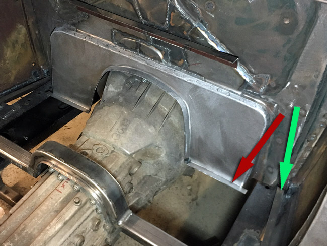
The filler piece between the firewall and the trans hump has been welded in here. The panel is rosette welded to the firewall and has small flanges to which the floor will be welded (red arrow).
|
|
|
|
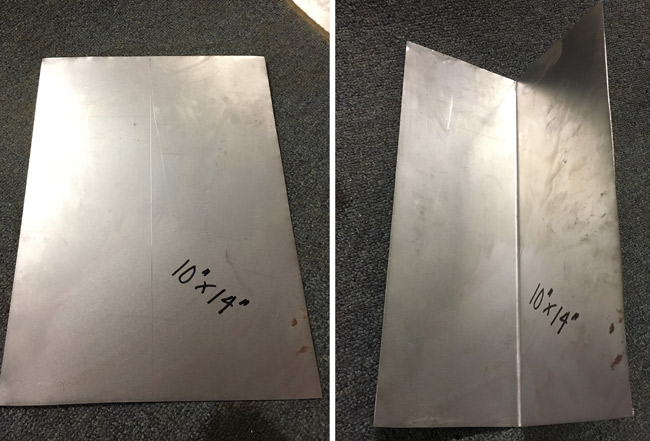
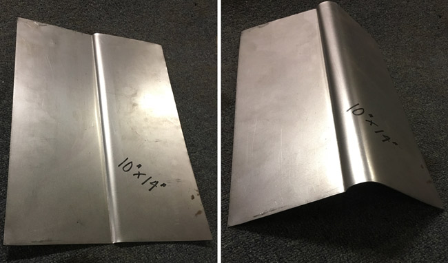
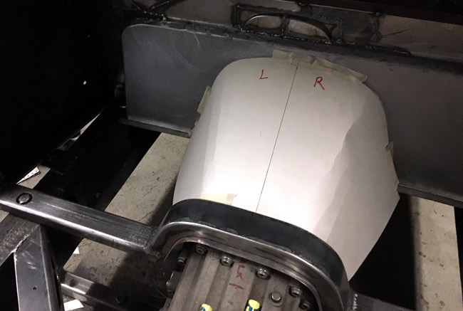
Work on the transmission tunnel was started by making a half pattern for one side. It was then copied so the pair made a complete pattern, and ajusted until it fit. The cardboard pattern was then traced onto a piece of sheet metal and cut out. |
|
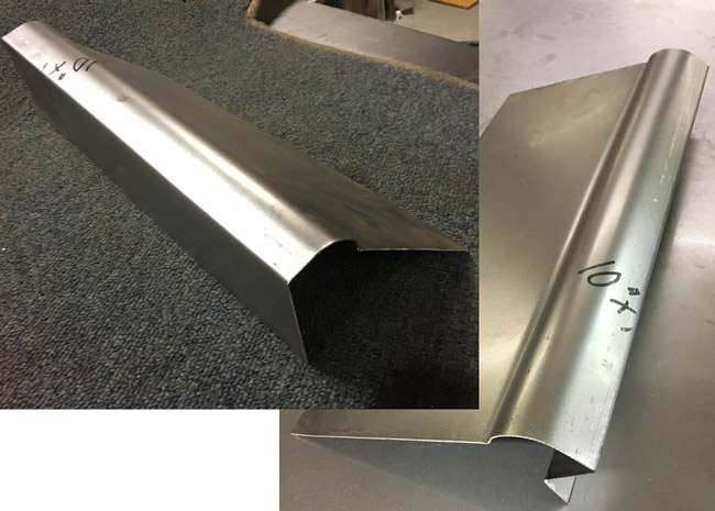
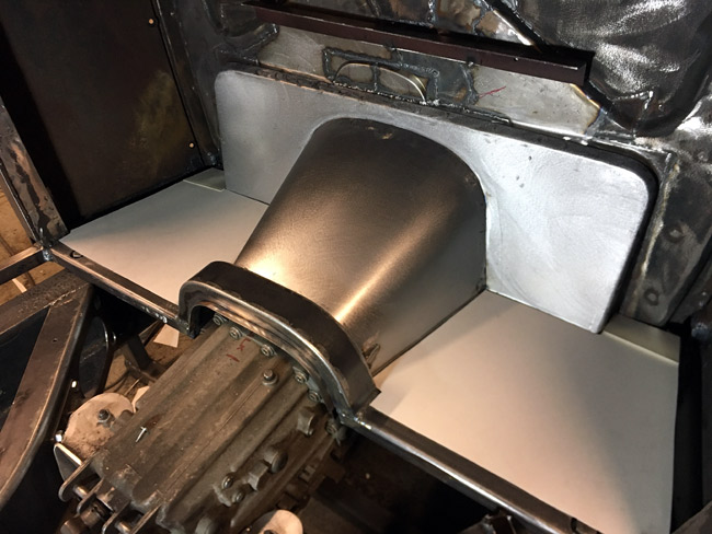
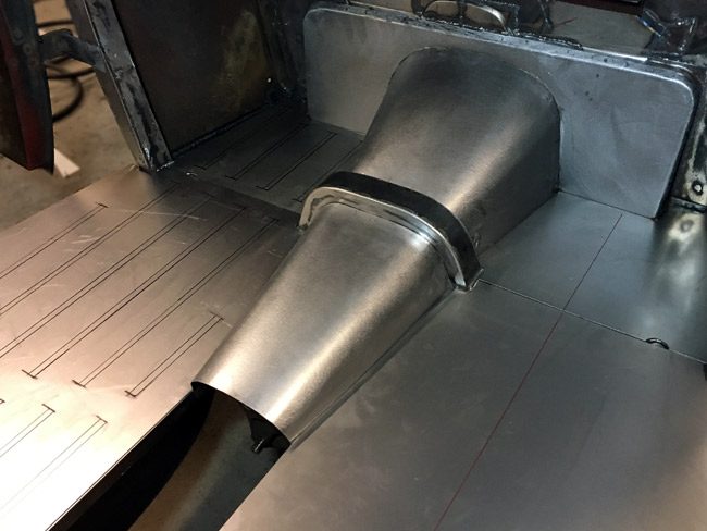
The front most part of the transmission tunnel is welded in.
|
|
|
|
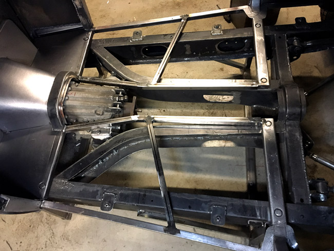
After a bit of panning ahead the 1" square tubes along the trans tunnel could be done. |
|
Work continued making the drive's side middle floor panel. The floor is a bit oversize in the door opening, since a piece that continues the bead along the bottom of the cowl and quarter panel has to be made. This whole thing has to follow the curvature of the bottom of the door. Only one of these parts came with the car, and it is severely rusted, and can only be used as a pattern. |
|
|
|
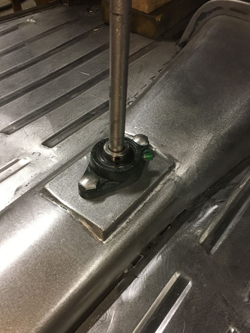
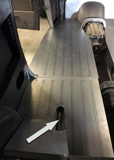
A hole is left in the floore here because the upper four link bars would hit the floor, so some
kind of "hump" will have to be made here. Arrow points to the link bar.
|
|
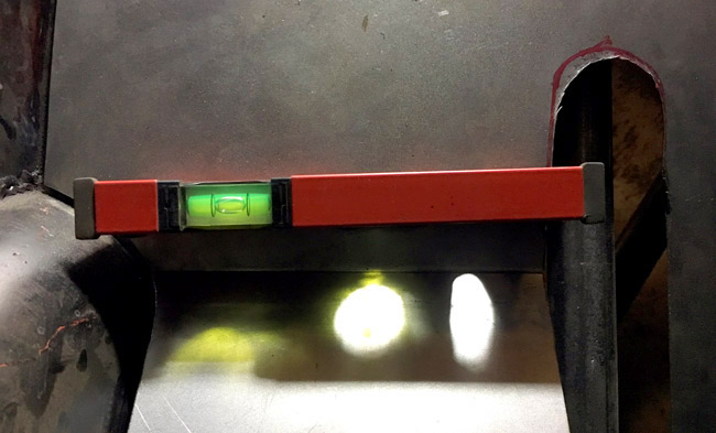
Floors are coming nicely, and using cardboard templates has proved efficinet, work is fast and the panels have fit first time, so far. The floors come out nice and level too. |
|
|
|
A 1" sqare tube was welded in between the wheel tubs, to weld the floor to, and to give it some structure.
This will be plenty strong when it's all welded into a unit.
The rounded corners were bent around a pipe.
|
|
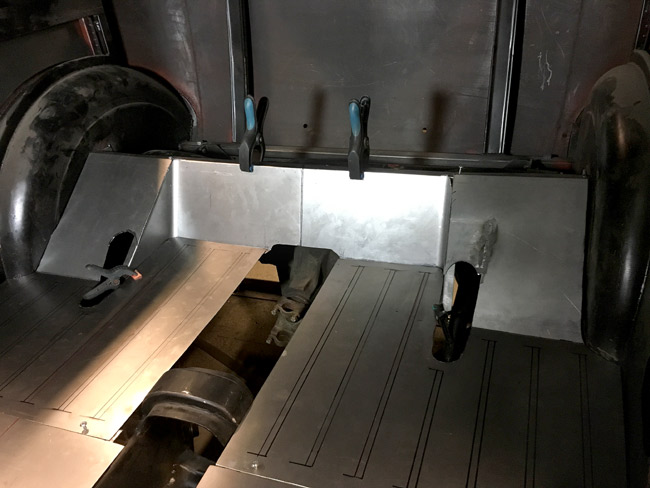
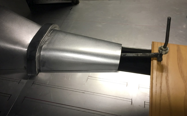
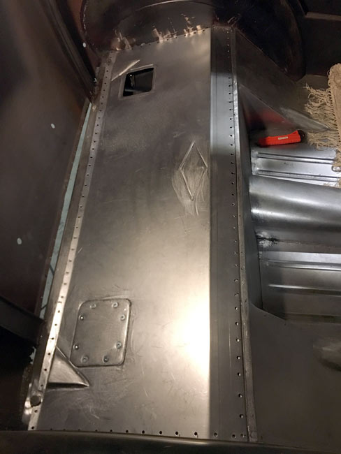
Template making work was commenced today, with the extension of the transmission tunnel. It's a tight fit all over since the goal is to be able to get three fairly comfortable pedals mounted. There is only about 3/8" to 5/8" of room between the transmission case and the tunnel. I would have wanted a shifter poking up somewhere in this second part of the tunnel, but the shifter will likely be further back. |
|
|
|
The shifter isway too far back now, but the longitudinal shift link can be shotened some 6". This will effectively move the shifter forward, so that the shifter boot will be about at the front of the seat. |
|
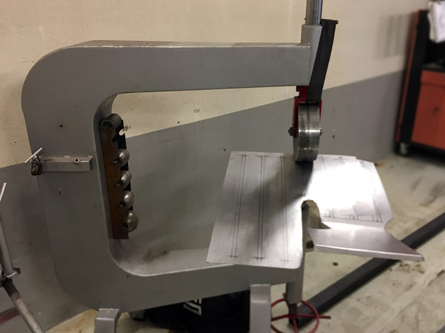
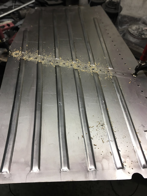
At a better equipped shop with some big offcuts to try some different style beads.
I kicked the wheel very tight and rolled twelve times over each line where the beads were going to be rolled.
|
|
|
|
Back home, the driver's side middle floor panel is tried into its place. These middle parts warped the worst, but they'll probably sort themselves out when they get welded in. The ends of the beads were tidied up with a hammer and a chisel ground to a dull square end with rounded corners. There, at the rear of the door opening, a square stamping was made. A fun little detail was needed for he floor, and this was it. |
|
A Body by Fisher plaque. It's a fun detail, and also original to this car and GM specific. This one's been on the cowl, where it was cut out along with some rust. |
|
|
|
So now there's a ton of drilling and plug welding to get the floors in.
|
|
A ton of plug welds done, and now there's some grinding to do. |
|
|
|
Both sides welded and the welds ground. Another part of the trans tunnel trieal fitted. |
|
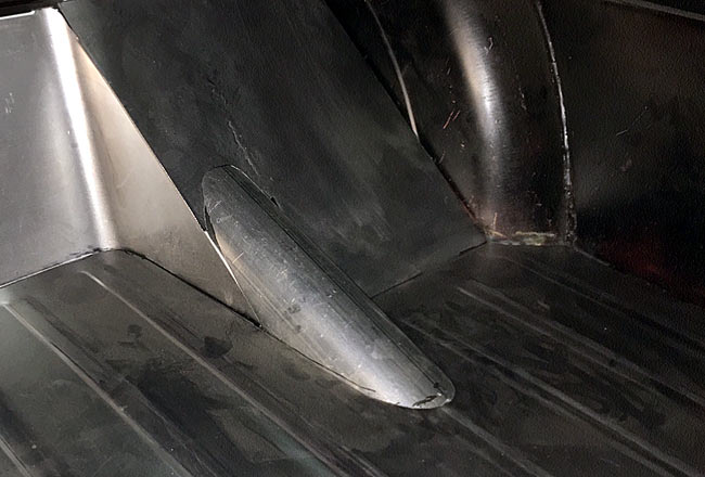
The link bars for the rear axle need room to articulate, and exhaust pipe is used to make these covers for them. |
|
|
|
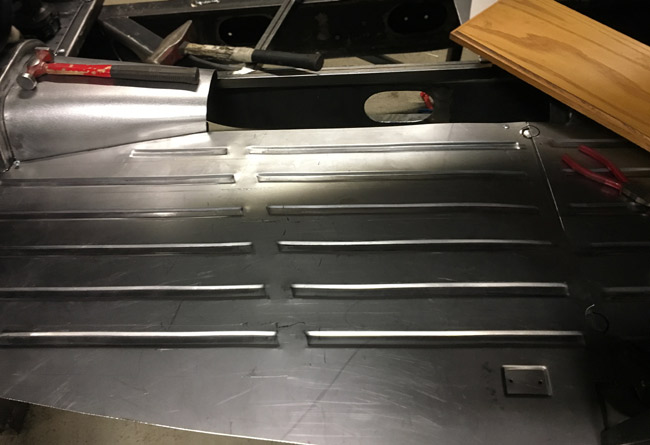
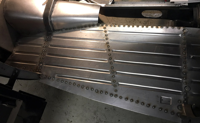
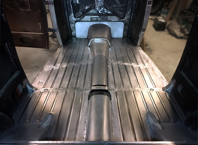
The floor is almost done, design idea accomplished: The beads are running front to back, in line and parallel. |
|
Rear most floor part, that comes under the rear seat, is done but still not welded. Small hatches are made so the rear springs can be serviced. |
|
|
|
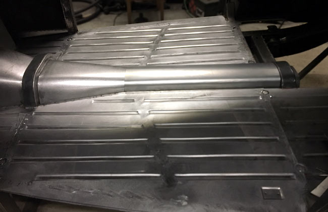
The basic shifter is in place, and another part of the trans tunnel is welded in. |