|
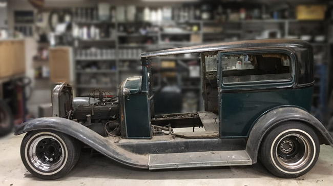
Page 2 The project begins |
some fresh steel in.
Starting from the front.
|
|
|
|
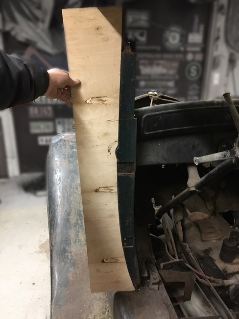
First the shape of the A-pillar was traced onto a piece of thin plywood and cut out.
This piece is then used as a template for the plasma cutter to cut the 1/8" thick sheet metal that the pillars will be built from.
|
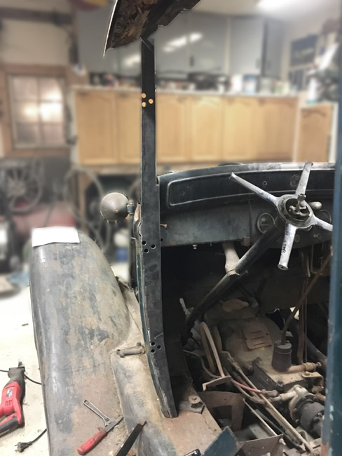
The new piece is trial fitted into its place, with holes drilled for the door hinge bolts, holes being over sized to provide adjustment
|
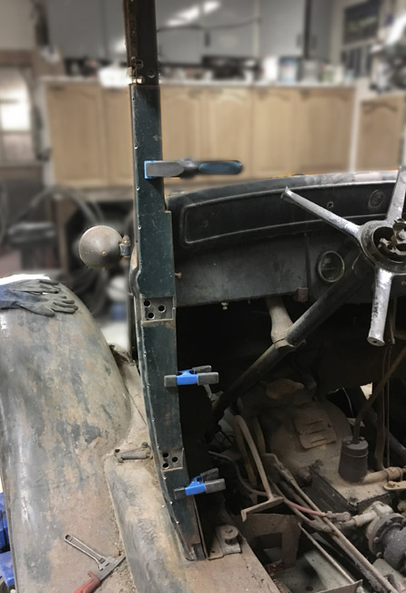
After tack welding the first piece of the pillar to the cowl, the sheet metal moldings are trial fitted. So far so good, so next up will be to build the rest of the pillar into a box shape. |
|
With the axles out from under the car, the stance could be tested for real. Looks like it needs to be lowered about 8" in the front and 6" in the rear. We''ll probably run into all kinds of problems to get it sitting like this.
|
|
|
|
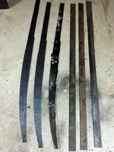
When the parts for the A-pillars were laid out on the floor, I realized they should have been built before being welded to the cowl.
|
|
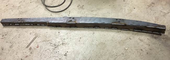
The right hand side pillar welded into a unit before mounting to the cowl. I didn't expect it to warp as badly as it did, and had to do a lot of shrinking by heating and cooling to get it reasonably straight.
|
|
|
|
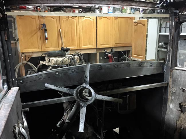
Next the width at the top of the pillars was determined with help of an original piece of sheetmetal that goes between the pillars, then braces were welded in. |
|
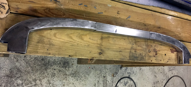
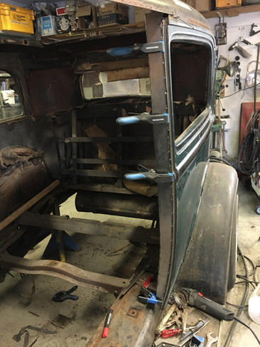
A piece of square tubing, rolled to a curve was welded to the cowl, and a new reinforcement piece (the sheet metal part with rosette welds along the top) was welded to the A-pillars. Now the whole structure is nicely rigid.
|
|
|
|
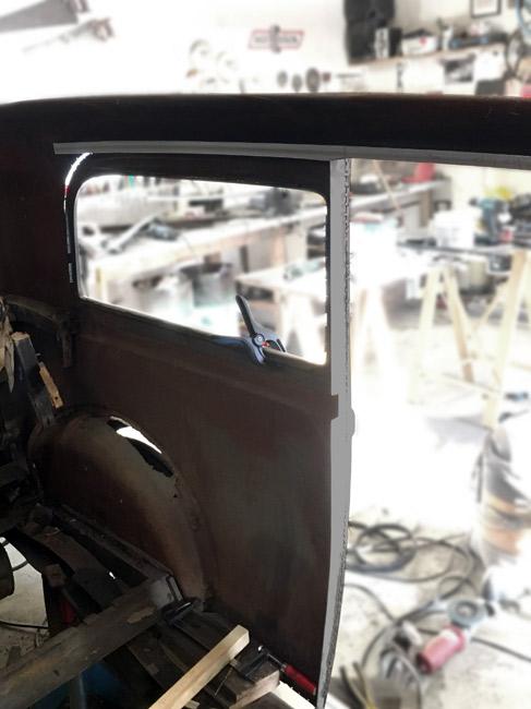
The whole windshield opening done with 1" square tubing (25x25x1,5 mm) with a flange added on the inside, for holding a rubber seal. A new windshield frame will be made, hung on hinges off its top, and will fit inside this opening. |
|
Turning to the B-pillar next.
|
|
|
|
|
|
|
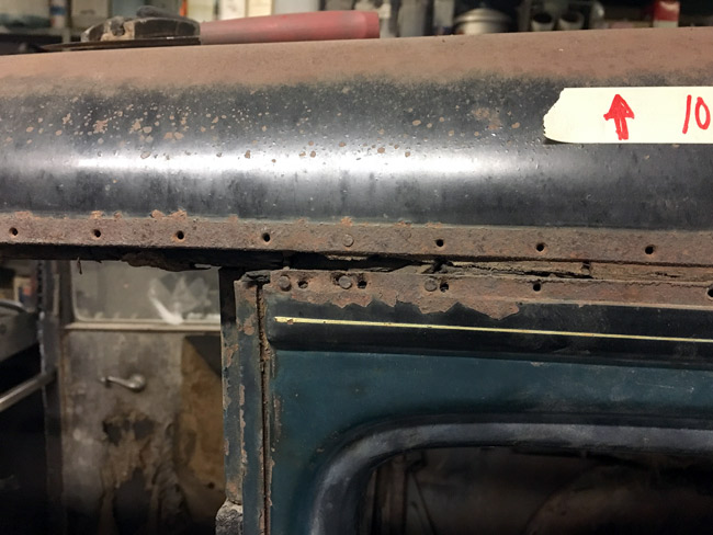
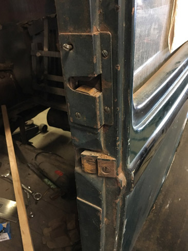
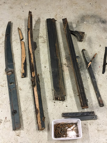
This shape of the B-pillar is what needs to replicated in the future. |
Sheet metal covering removed. |
Old B-pillar structure. |
New B-pillar under construction. |
|
|
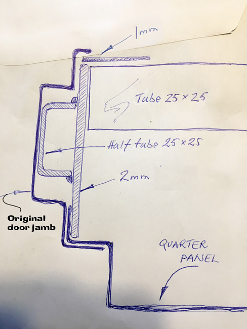
This sketch shows the plan for the driver's side B-pillar seen in a top view. |
|
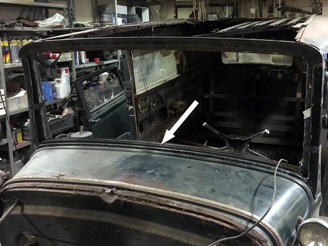
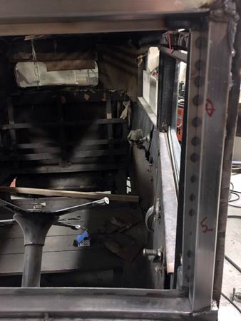
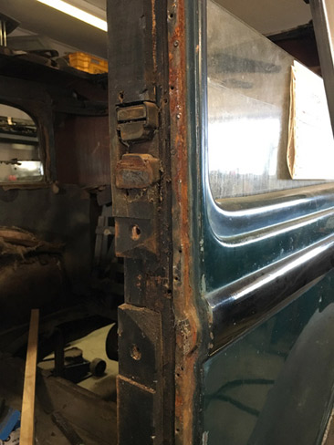
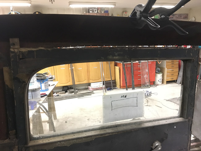
Inside view of a quarter/rear side window. It's all framed in wood, so there's going to be a lot of planning and fabrication work to get this to look okay and work right. As seen here, the rear side windows open, and of course that's a feature that has to be retained. |
|
|
|
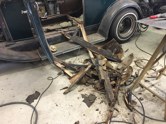
Finally all the wood from the rear of the body is out.
|
|
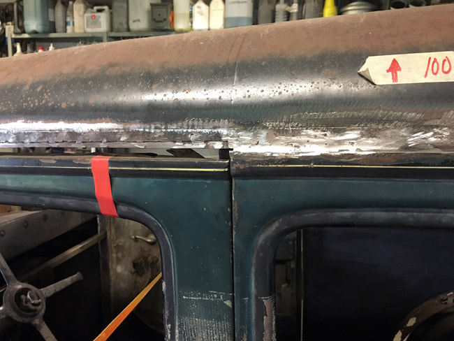
As seen here, a piece of square tubing has been rolled to a curve that fits where the body side and roof parts meet. |
|
|
|
Same view as a few pics back.
|
|
There will be a slightly curved tube along the roof connecting the B-pillars. Here are the end pieces, with some tubing to show the principle. |
|