|
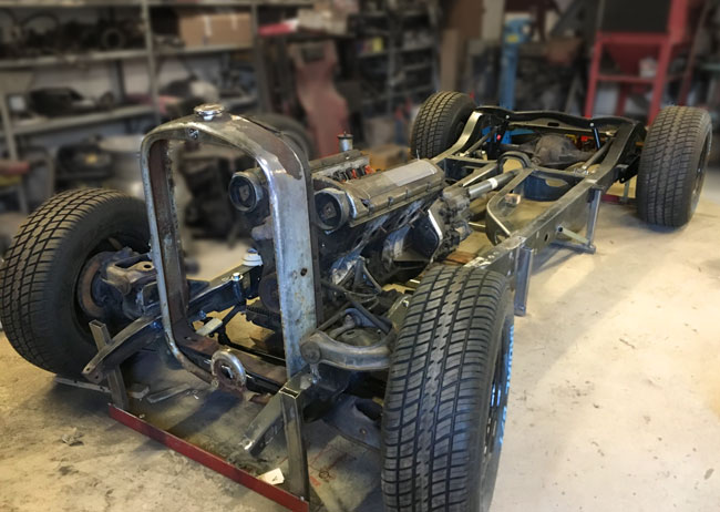
Page 2 The project begins |
|
|
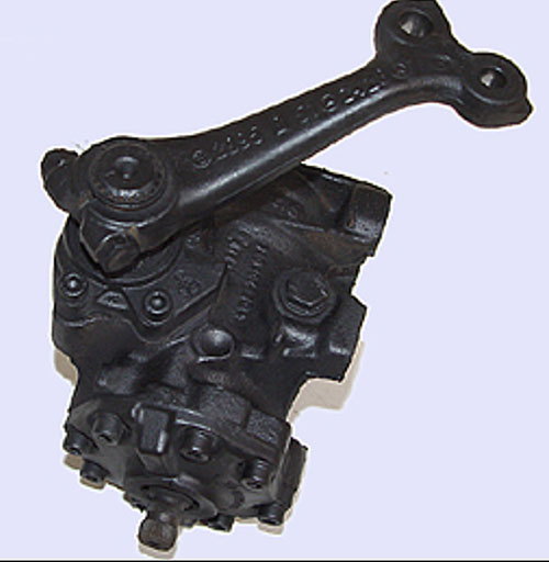
Since the front suspension has been of the front steer variety (rack and pinion in the front of the axle),and we're going with steering box and idler arm in the rear of the axle, we're facing some problems with the ackerman angle. Easy as it seems, the knuckles or spindles are mounted on the wrong side, to bring the steering arms backward, instead of forward. Generally this is seen as bad practice, since the ackerman angle will be negative. In effect, if you'd just mount a steering rack behind the axle, connect it to the steering arms and calling it a day, the steering would act very badly driving in a turn. Bending my mind around this issue, I have come up with a few solutions, some of which haven't been really practical. Some time ago, the solution was foundin a pic of a Mercedes w124 steering box. In this pic the Mercedes box is upside down so the pitman arm can be seen. Since this resembles the cnc arms I had already ordered, this would work. All OE parts, this would be safe to use. |
|
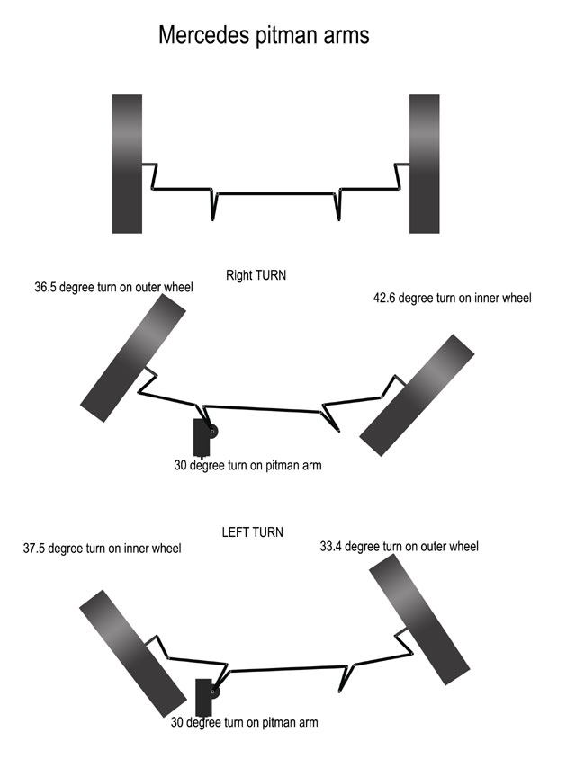
The other day all the relevant details were measured, and a very exact sketch drawn up to test the geometry. According to the sketch, there should be no doubt that the ackerman will work as it's supposed to. In the sketch the pitman and idler arms look like a V, but the measurements are correct and correspond to the actual parts. It's taken a lot of thought to come up with this solution, but it is necessary since there is no room for a steering rack between the front axle and the grille. |
|
|
|
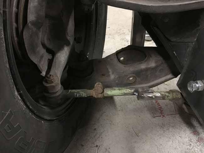
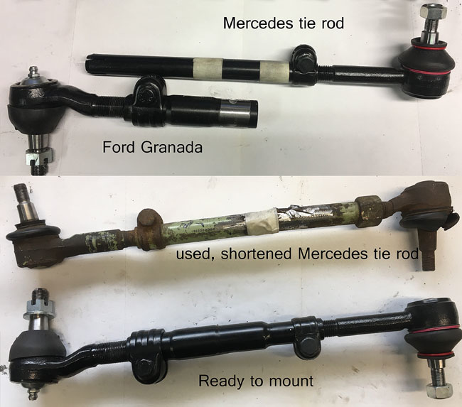
Real world measuring of the angles proved that toe out on turn is achieved.
The rod in the pic has been tack welded into many different lengths for this experiment.
|
|
The tie rods were made by pairing Ford and Mercedes tie rod ends together with a new adjustment sleeve. |
|
|
|
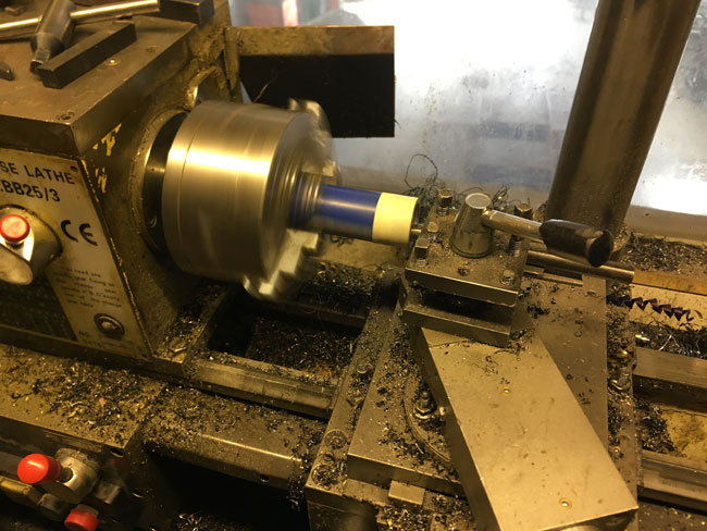
To make a housing for the idler arm bushings, the inside diameter of a piece of steel tubing had to be slightly enlarged on a lathe. |
|
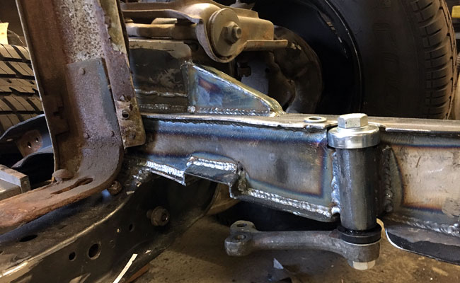
Because the idler arm had to be inset into the frame to make for a good geometry, an 8" long doubler plate was welded into the center of the frame rail, and the idler arm bushing housing in turn welded to it. Then the "real" boxplate was welded to the frame and to the housing tube.
|
|
|
|
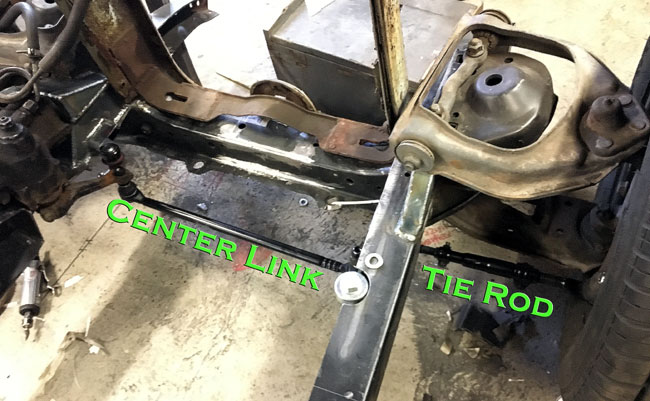
This is what the completed steering setup looks with all parts in place
|
|
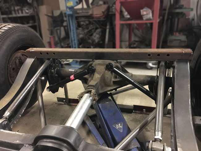
The rear shock absorber cross member was made from a piece of 1/8" wall 2-3/8" square tubing.
But no, we cant have a straight tube for a crossmember after all the work put into the rest of the chassis. |
|
|
|
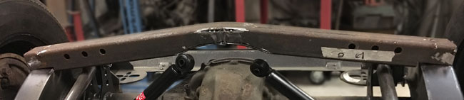
It was cut up and work started with a curve in the top. |
|
The result is a crooked piece of tubing, holes cut in the bottom to mount the top eyes of the shocks inside the tube.
|
|
|
|
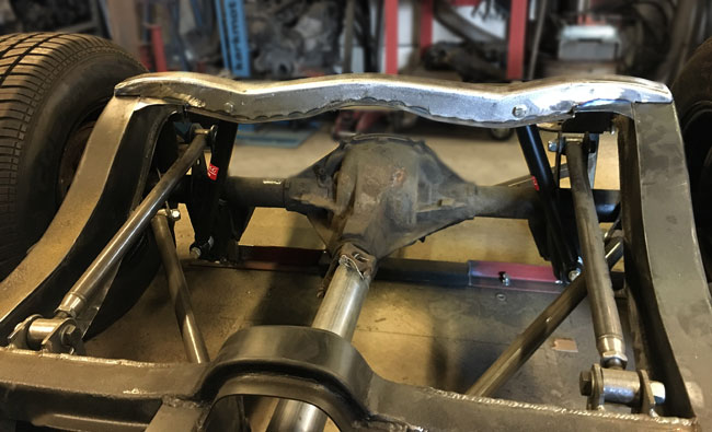
The new crossmember fits right in. |