
|
Page 2 The project begins |
|
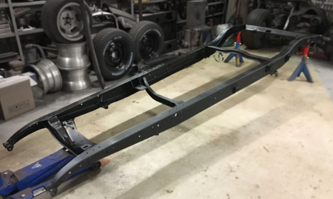
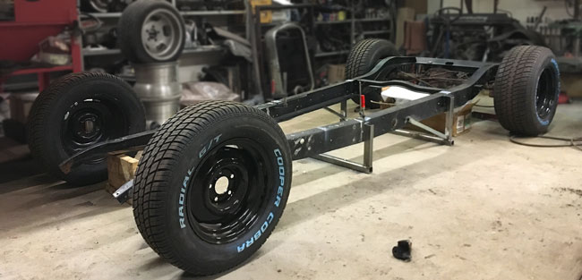
The frame came back from the sandblaster's with a thin coat of rust preventive primer. It looks great, and has surprisingly little rust, considering it's 92 years old.
|
|
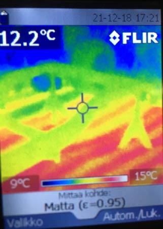
A friend working in construction came over with an infrared camera, and marked the floor where it was safe to drill holes. The frame is going to be bolted to the floor, but as we have electric floor heating, I didn't think it was even possible. Here's a pic of the viewfinder on the infrared camera. The frame and jackstands are yellow-greenish. You can still see the warmer red lines in the floor, those were much sharper earlier, when the heat had just been turned on. |
|
|
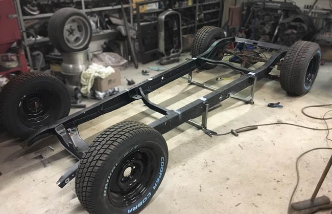
This is like a frame jig, as the frame is welded to uprights, that in turn are welded to thick wall square tubing, and those are bolted to the concrete floor.
|
|
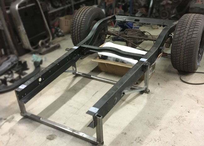
The frame was cut about 9" behind where the fire wall will be. It will be bent up 2-1/2 inches at the front crossmember. This will make it possible to run a lower front end. The frame is cut/bent as far back as possible to make the bend angle less acute so the result will look close to original. |
|
|
The frame is mocked up to the right height and width, pinched 2" at the front axle.
|
|
Some cutting later, the new front cross member could be mocked up on the frame. A bit of grinding and adjusting now, and the frame and crossmember can be tacked in. Lots of measuring, and making sure everything sits right before that, though. |
|
|
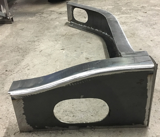
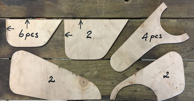
New rear kick up to clear the rear axle. The upward travel will be almost 6 " from ride height. The kick up will consist of two pairs of these cut out of 1/8" sheet metal. welded up with flanges, they will form a boxed structure. (January 2022) |
|
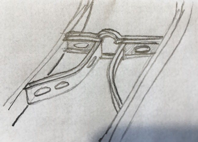
A sketch of the planned K-member. It to will mostly be made of 1/8" thick sheet metal. |
|
|
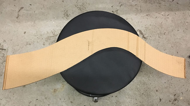
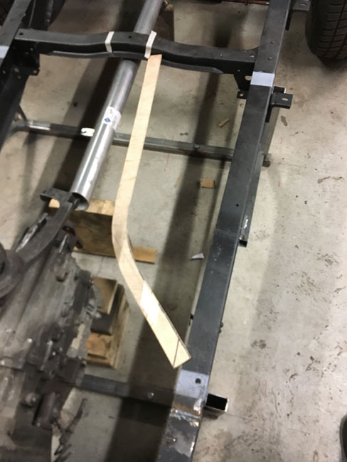
Here's where the top flange of the K-member will go on the frame. This is a plywood cutting form for the plasma cutter. It's a simple and efficient way to cut multiple pieces of the same shape. The old crossmember (at the top of this pic) will have to be modified in the center, between the white pieces of tape. The prop shaft needs a few inches more room to move up. |
|
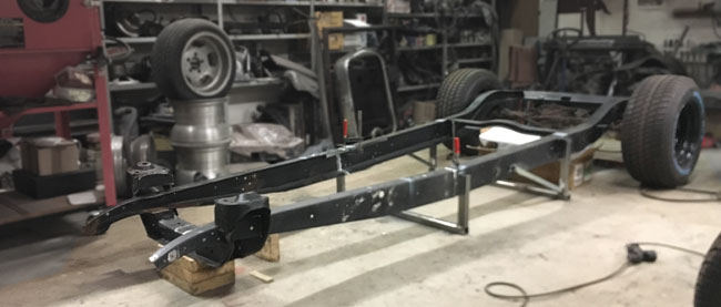
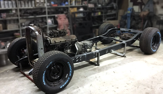
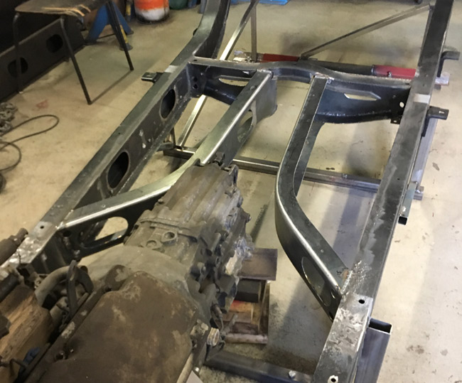
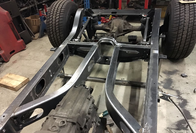
The frame is welded back together, the new front cross member is welded in, nice and solid, and the front end of the frame is also welded to uprights bolted to the floor. The engine and transmission were mocked up together with the adapter plate, and the whole package hoisted into the frame and spaced up from the floor with wood, to get it inti the approximate right posistion. There's still some probelm solving to do, to make everything fit and work. |
|
|
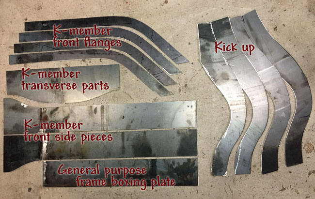
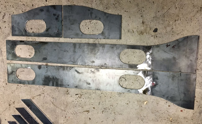
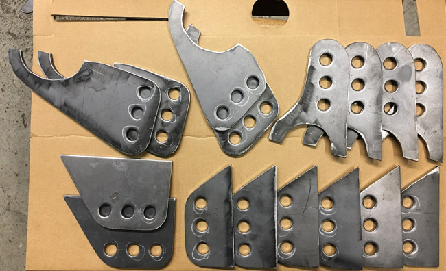
Using plywood templates, a bunch of parts were cut with the plasma cutter.
Designing the parts, where to mount them and planning the cuts to optimize the use of the sheetmetal, actually cutting it, and then cleaning up the cuts with a grinder... this little heap of parts took a good while to produce. |
|
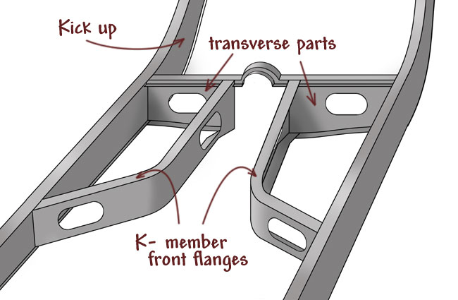
Here's an updated sketch of the K-member. The boxing plates are sized to step into the frame, which will look nice. They will get matching oblong holes cut too, to match. Mufflers will probably be mounted "inside" the K-member. The rear axle triangulated 4-link bottom bars will mount to the K-member at the bottom center in the back, hence the dip towards this area. The frame will ride relatively high, so there will be about 8" of ground clearance under the frame at rideheight. |
|
|
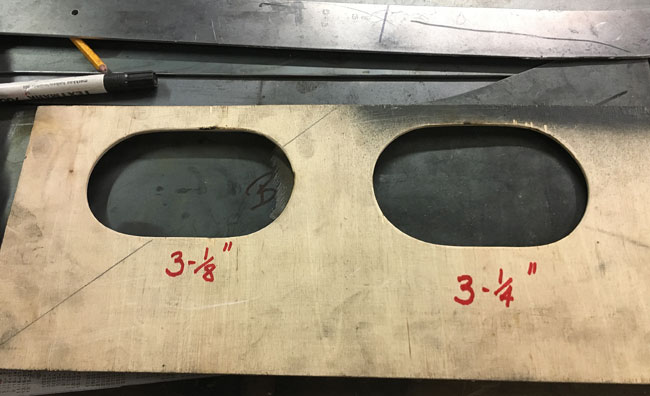
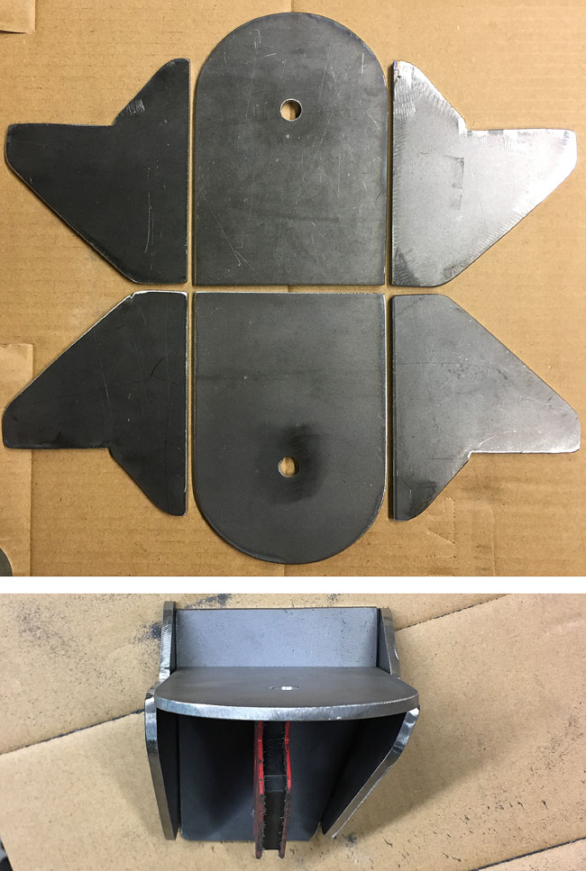
Another plywood template was made for cutting different size holes in the K-member. The template is cut so that aligning one side of it with the side of the K-member piece, will put the hole in the middle of the part. |
|
Holes cut. These pieces are ready for tacking together. |
|
|
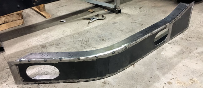
Bending and tacking done here, to get this first part of the K-meber coaxed into its designed shape. |
|
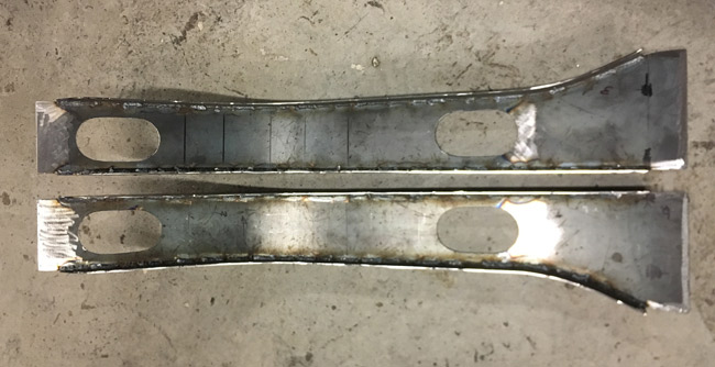
All welded here on the inside, the outside of these will be ground to get nice round corners. |
|
|
The edges were ground, and on the whole, things start looking like planned. |
|
Again, seen from the rear, the K-member will be welded in like this, after the frame is boxed.
|
|
|
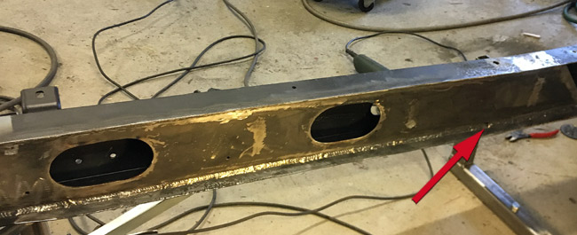
Box plates welded in on both sides. They are only abit more than 50 inches long, but they will cover the length needed to weld in the K-member. The arrow points at a drain hole made by grinding a 3/4" wide round slot at the edge of the plate.
|
|
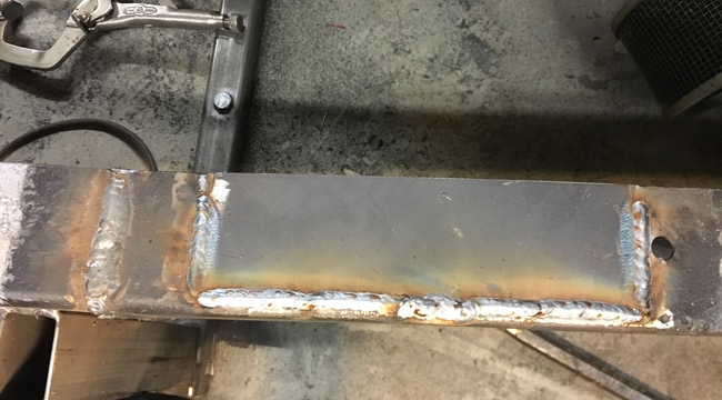
A great thing about this frame is that it's in such good shape that only a 2"x 8" piece was needed to be cut out in the top flange where rust had bit. Pretty amazing, the frame is 92 years old after all. |
|
|
Another plate was cut out to fit behind the K-member, jigged in place here ready to weld in.
|
|
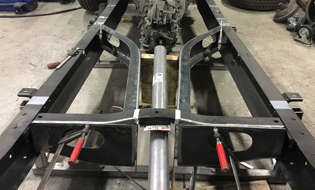
The kickups were boxed too. The springs and shocks will mount to the rear of the axle, so the frame needs to be pretty rigid all the way here. |
|
|
Finally the K-member could be welded in.
|
|
The axle was measured, centered and squared in the frame, the pinion angle at 3 degrees, same as the engine and transmission. |
|
|
A bunch of plywood patterns were cut out, for cutting out the brackets for the four link.
|
|
Fortyeight 5/8" (16 mm) holes were punched into the brackets. This took the guy at the metal shop all of ten minutes. Drilling them out in this 3/16" (5 mm) material would have taken me hours. Actually the holes were a tiny bit undersize, and just drilling out the last few thousands took me almost an hour, with a new drill bit. |
|
|
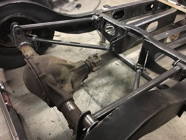
The rear axle in its place after the brackets have been tack welded to the frame and axle. The suspension travel was tested, and there's no binding. |
|
More cutting and grinding. This is what will be the lower air spring mounts. In the bottom pic one of the mounts is mocked up with a magnet. |
|
|
The right hand spring mount welded. |
|
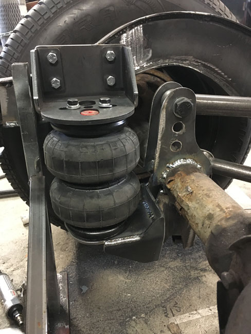
The complete air spring setup. A bracket was made, with 3/8" unc nuts welded to it, then welded to the frame. The upper mount is bolted to this bracket. |
|
|
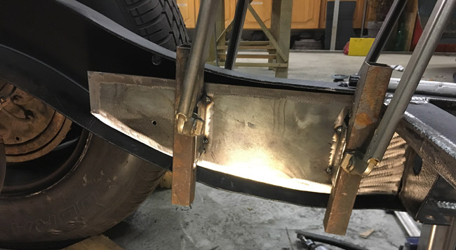
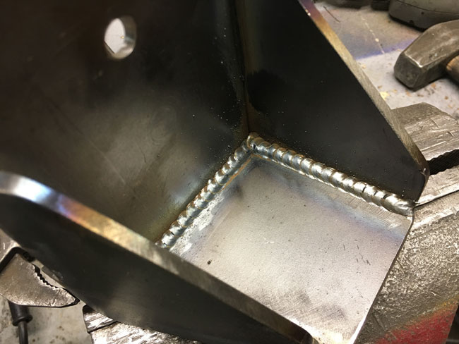
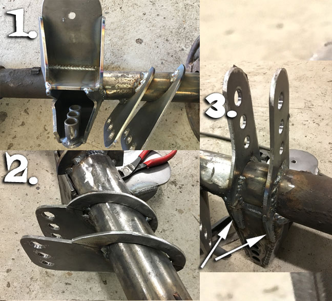
Everything but the shock absorber crossmember fitted now, so the axle came out for proper welding. As seen in pic #1, the axle mounts got to be pretty busy looking. This is a bottom view, the axle is upside down on the floor. Lots of welding, and very time consuming, as we don't want too much heat in the axle tube, and have to take frequent breaks. Pic #2 shows the "rings" that connect around the axle. The idea being that if an equal amount is welded all around the axle it might shrink about the same. Here the axle is right side up again. Pic#3 shows a couple small gussets that reinforce the connection between the upper four link brackets and the shock mount. |
|
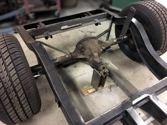
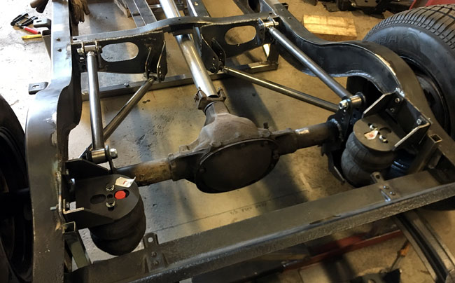
Finally the four link brackets are done. A lot of welding and a bit of grinding later the axle sits back in the frame. Just a squirt of flat black over the brackets to keep them from rusting. The axle will probably be sand blasted before paint. Shocks with their cross member still lacking. |
|
|
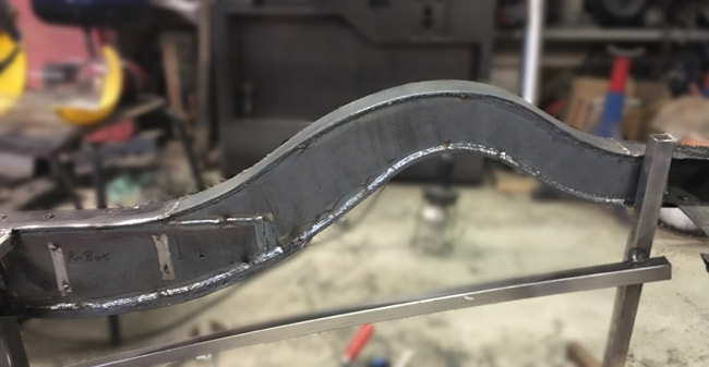
The K-member is ready as it will be. It's all connected in the center now, the bottom part is cut off of the original front cross member and the top part is made from steel plate, continuing the same profile as the original crossmember. Again the thought is it would look like it could always have been there. |