|
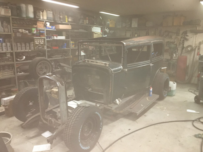
Page 2 The project begins |
|
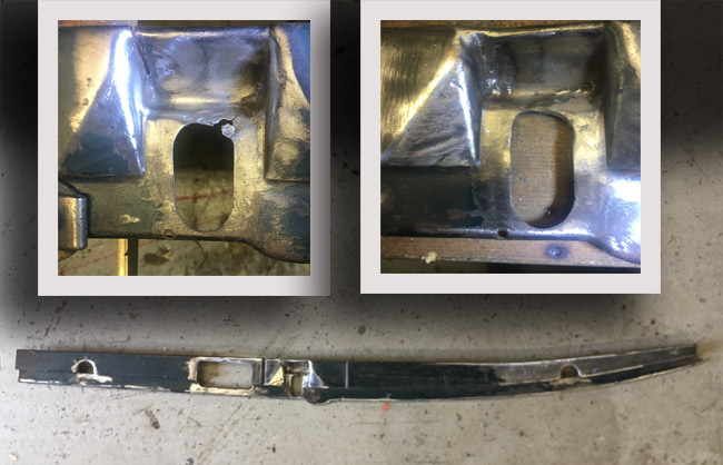
The door jambs are next on the agenda. The driver's side one was welded in already, but as the car had been in an accident, the right hand door jamb piece casued a bit of sheet metal work. The bottom part was badly out of shape, and the part where the lock strikes was cracked.
|
|
|
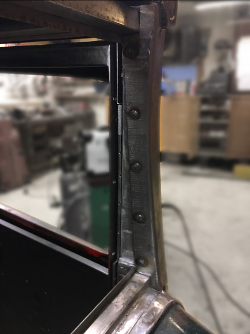
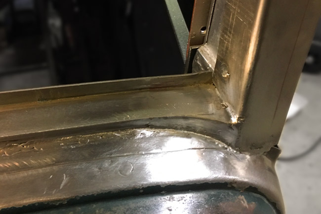
The door jamb rosette welded to the B-pillar |
|
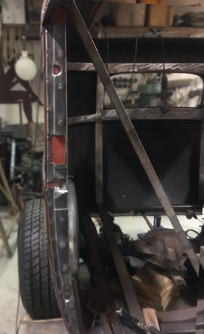
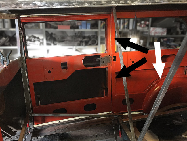
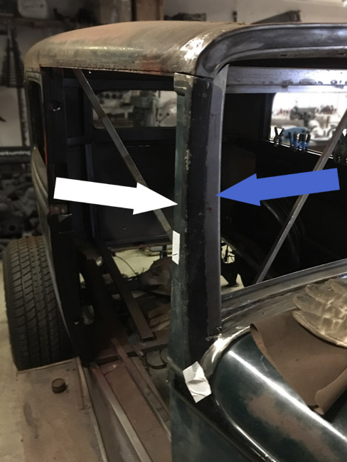
Now the inside of the B-pillar could be finished (black arrows). a strip of sheet metal was welded in to make the top of the pillar look finished, and the lower part is now able to take fasteners for the upholstery. Strips of sheet metal was welded to the wheel tubs too, for attaching the inside panels and upholstery (white arrow). The new sheet metal actually started flash rusting, so everything was sanded and painted with primer. |
|
|
|
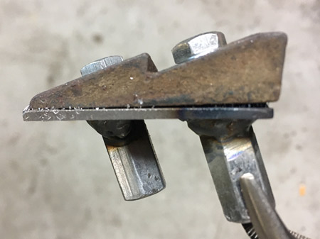
The latch strikers had to get something to attach to, so long nuts were cut to an angle and welded to a piece of 14 gauge sheet metal. These were then inserted into the little hole visible aft of the lock in the pic above, between the black arrows, and the strikers were mounted using counter sunk philips head screws. |
|
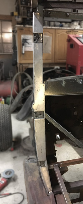
As the B-pillars were done for now, attention was turned to the A-pillars. After removing the door, some previously done welds were ground as needed, and the old sheet metal cladding pieces were drilled and rosette welded to the pillar. |
|
|
|
Continuing on the front side of the A-pillars.
|
|
The piece of sheetmetal was bent on a brake, and one of the sides was stretched to make it curve to match the cast part. This was then rosette welded to the windshield frame as it's not a structural part. |
|
|
|
A design with a more rounded end to finish it off was decided on.
|
|
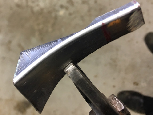
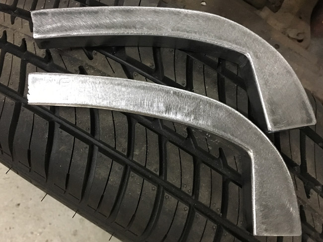
Here's how that rounded detail at the bottom of the windshield was made. A piece of 1" square tubing, a bit more than half cut away, and bent with the stretcher. Lots of work for a little detail, and of course, but it does add a bit of nice detail. |
|
|
|
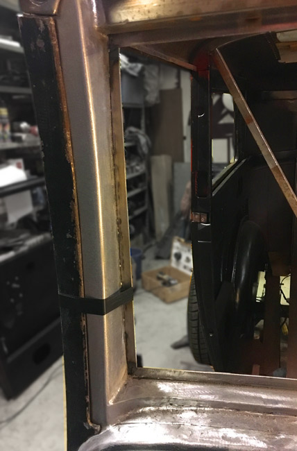
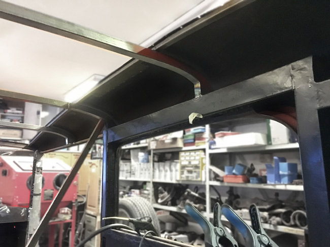
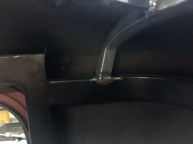
In this pic the piece above is already welded in, and the A-pillar is otherwise finished for now, the original cast pillar piece taped in place. The little frame/edge on the inside that will hold the seal for the windsheld frame is also done now. |
|
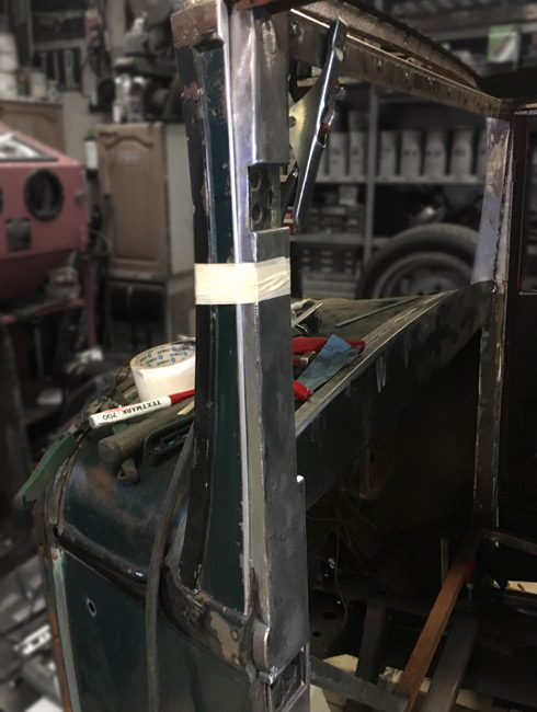
The driver's side pillar has gotten a bit of detail work done to it too.
|
|
|
|
The A- and B-pillars are done for now. Just the roof structure to do before pulling the body off the frame.
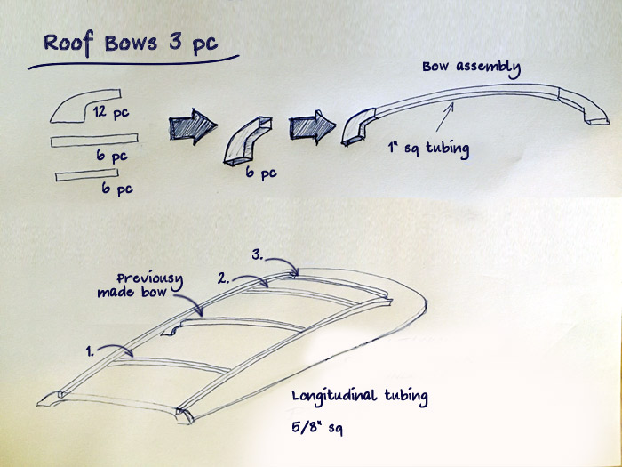
Three more roof bows will be added and attached to the framing above the rear windows and above the door openings. One previously made bow has been there for some time, functioning as a brace, to keep the A-pillars the right distance from eachother. |
|
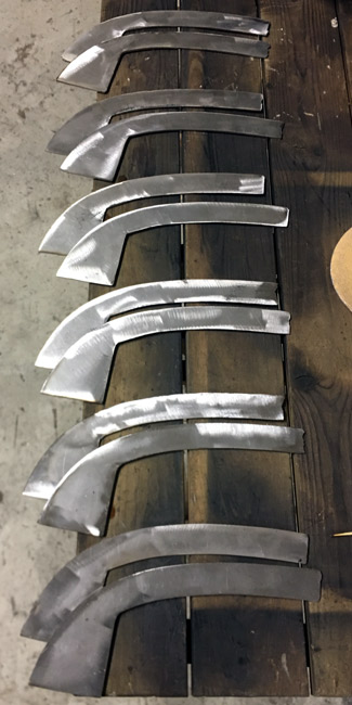
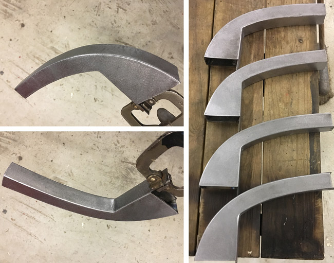
The end parts for the roof bows were cut with the plasma cutter. The twelve pieces are ground in pairs, so they'll go together square. The straight pieces were also cut, and welding these up is next on the to do-list. |
|
|
|
Bow ends welded into units and ground. |
|
|
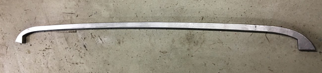
A complete roof bow here, prior to welding it to the body. |
|
As the longitudinals were going to be welded to the roof, the surface rust was removed with a wire wheel on an angle grinder. A side effect was this dense fog in the garage. |
|
|
|
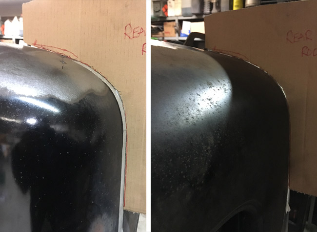
When the Buick was built, it seems the body wasn't checked for symmetry very thoroughly. It has been wrecked to some extent too. The rear of the roof was pretty different from side to side, it was almost ½" higher on the driver's side. |
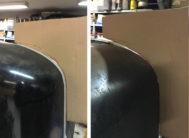
|
After a bit of slicing, welding and hammering, the roof is now more symmetric than it was before. |
|
|
|
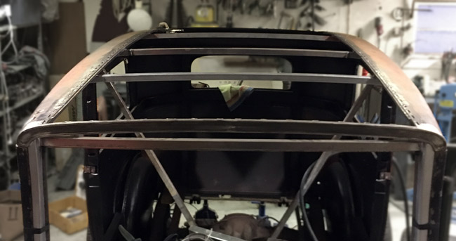
Here the longitudinals and two front bows are welded in. |
|
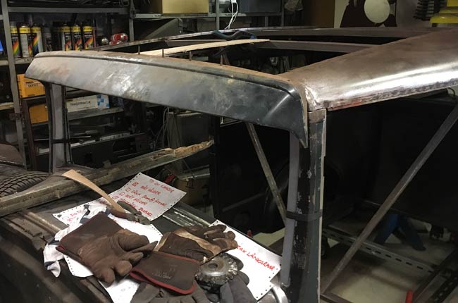
The ends for the rearmost roof bow are shaped differently, as the roof rounds off back there. |
|
|
|
The little vertical section of the roof bow ends might be useful for attaching inner panels. |
|
The rear roof bow was welded to the inner structure in this slanted position for the bow to follow the roof line. |
|
|
|
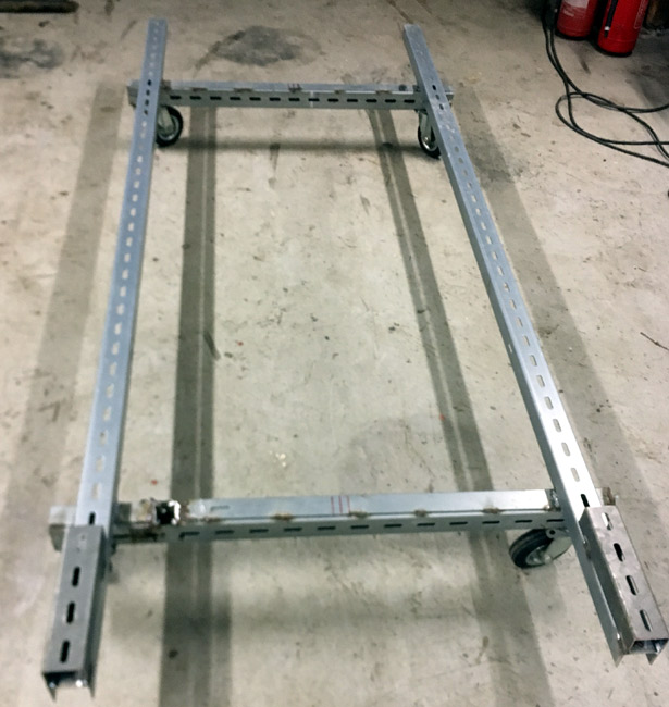
A rod builder gave me his body dolly, and after cutting it up an rearranging, it will now fit the Buick body. |
|
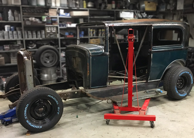
Engine hoist ready to lift the body off the frame, now just awaiting some helpful hands to keep the balance. |
|
|
|
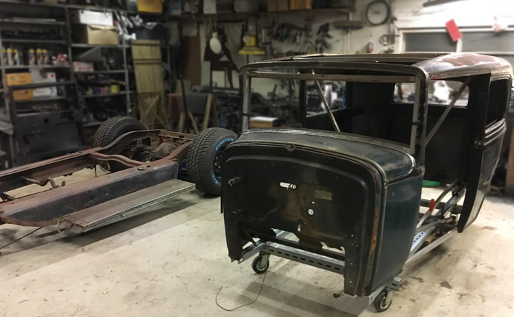
Finally the body is off its frame. Nice to have a sound structural body that keeps its shape. It would have been all but impossible to lift the body off the frame when the wood was first removed, as it would probably just had fallen into a heap of crooked sheet metal.
|
|
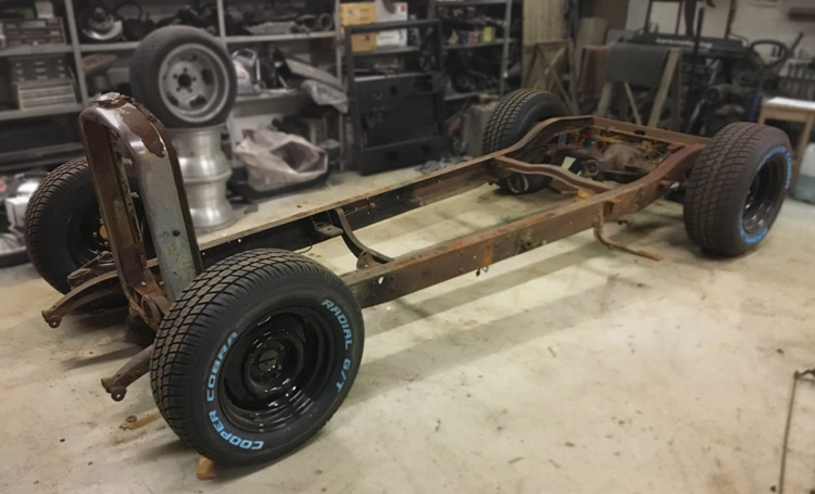
The frame looks simple and nice here, it's like a blank canvas with unlimited possibilities. |
|
|
|
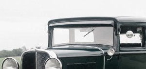
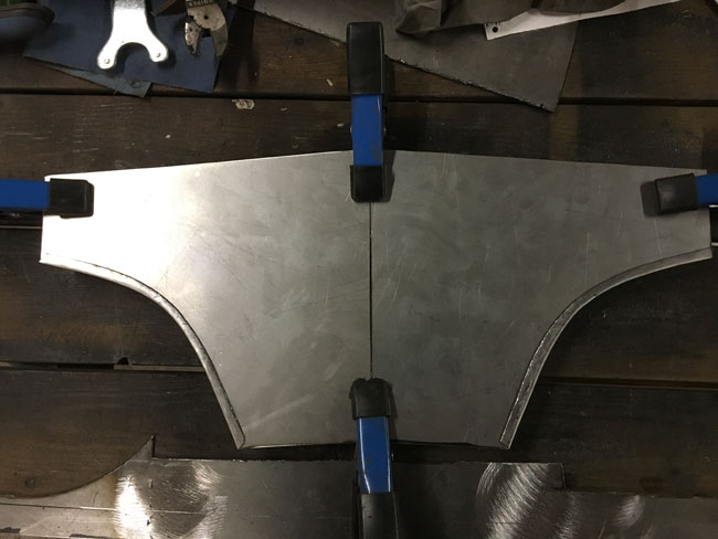
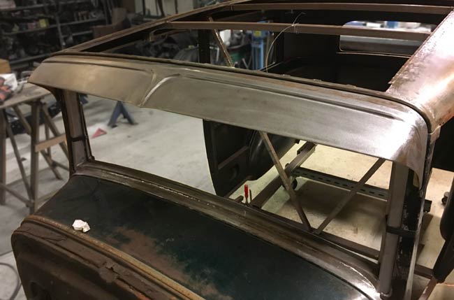
The frame is off to the sand blaster's, and to make use of the time we took a look at the visor. It's is narrow because it has fit between the outer A pillars, so the plan is to widen it and angle it up a bit. |
|
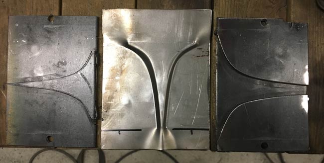
As the visor had to be cut in half anyway, a peak detail was going to be added to the center of it. First a press form was made from 3⁄16" thick steel sheet to make the desired shape. |
|
|
|
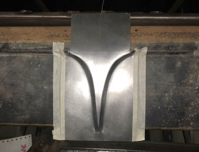
After some adjusting of the press forms, the second try was a success. Here the new part is taped to the center of the visor. |
|
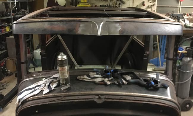
After quite a lot of hammering and grinding, here it is welded in. The visor got lengthened by about 1-5/8". |
|
|
|
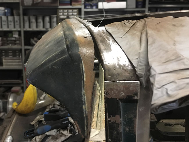
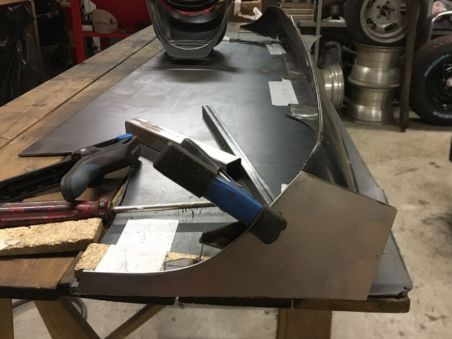
To gain a more streamlined look to the visor, the plan is to angle it up a bit like this. |
|
To get the desired angle, new ends have to be made to the visor. Here the pair of new ends are under construction. |
|
|
|
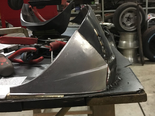
The new end part cut close to its final shape, and trial fitted to the visor, to check if the design will work. |
|
Some hammering, shaping and cutting later, the new part almost fits. The step bead was continued off the top of he visor, rolled into the new sheet metal, once again with the bead roller. |
|
|
|
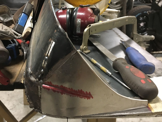
Once it was done, the work had to be done again, on the other side. |
|
All welded and ground smooth, ready for body work. |
|
|
|
This is what the visor looked like originally. Now, as it's moved up, lengthened and angled up, it looks a lot diferent. |