|
Page 2 The project begins |
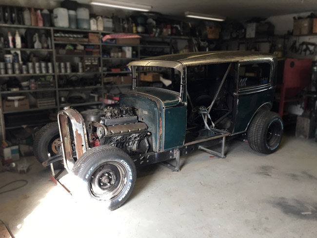
Body back on frame.
|
|
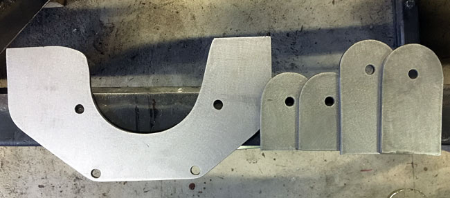
Parts for the engine and transmission mounts cut out from 5 mm (3/16") steel plate
|
|
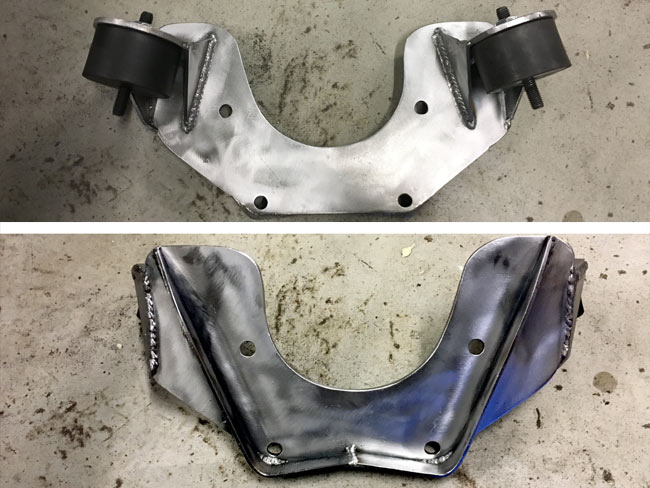
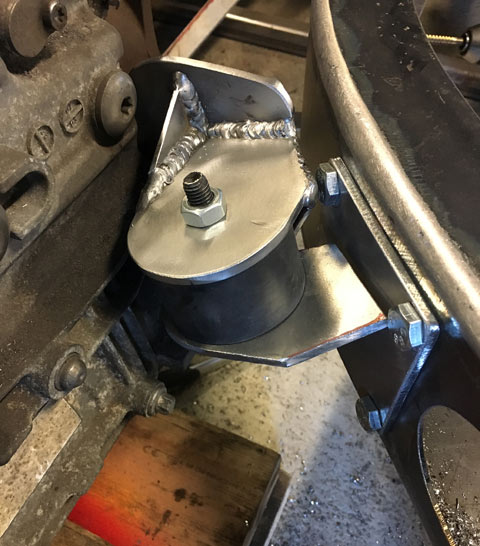
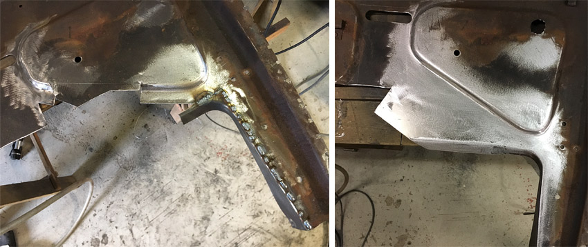
The finish welded transmission mount seen from both sides. |
|
|
|
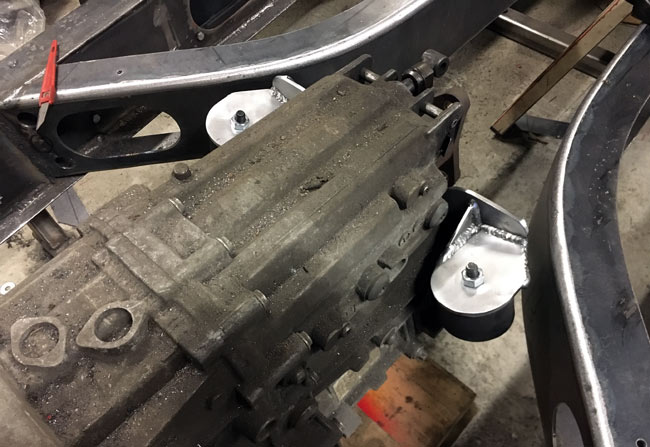
The transmission mount bolts to the rear of the transmission case. |
|
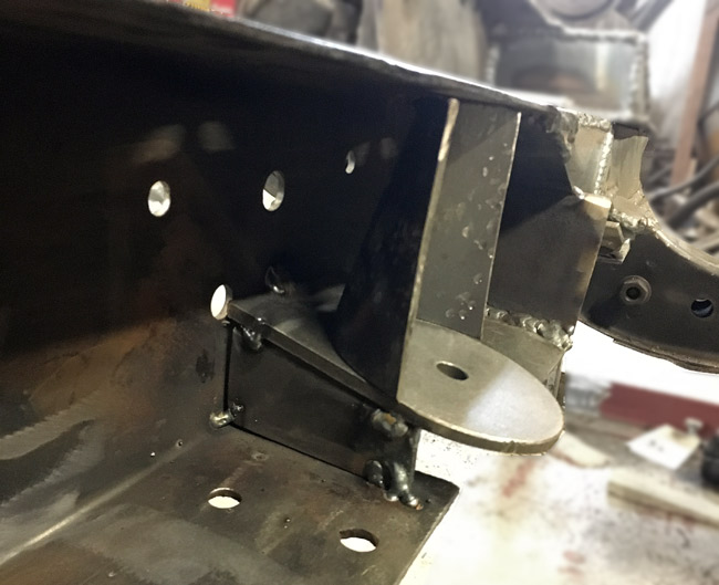
The chassis mounts are removable from the K-member to get the transmission out downward in the future. |
|
|
|
The removable chassis mount finish welded |
|
The engine mounts were tacked in using a mirror, hence the unsightly tack welds.
|
|
|
|
Round parts to continue the box plate around the engine mounts were cut and hammered to this shape. |
|
Box plates were cut to size and welded in.
|
|
|
|
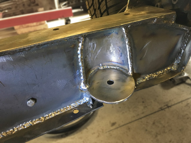
The vertical welds both sides of the engine mount will be ground off later. |
|
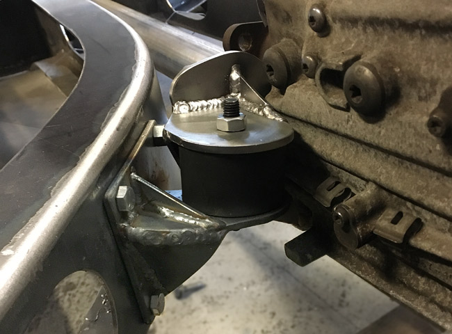
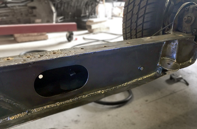
This is what the engine mount looks like mounted to the frame. |
|
|
|
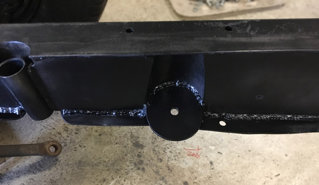
After the vertical welds were ground smooth, the box plates look much tidier. |
|
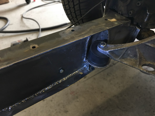
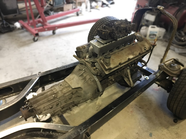
Finally the engine and transmission could be mounted to the frame on proper mounts. |
|
|
|
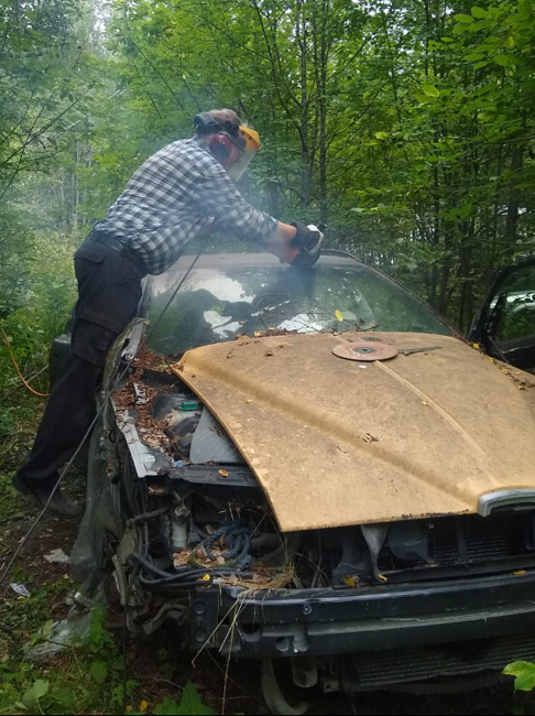
After a lot of measuring and looking for suitable donors, the roof of an early twothousands Volvo V70 looked promising. Cutting the roof off of a junked Volvo wagon. |
|
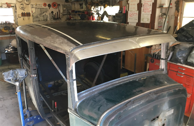
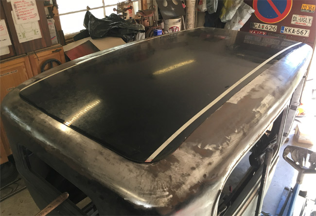
When cut out as close to the edges as possible and turned backwards, the roof lays surprisingly nicely on the body. |
|
|
|
The roof lays down completely flat against the body except in the very rear at the coners. When it's final cut to fit in its place it will likely lay almost totally flat. The roof will be welded on after the body is shimmed and adjusted and bolted to the frame, so we'll get back to it later. |
|
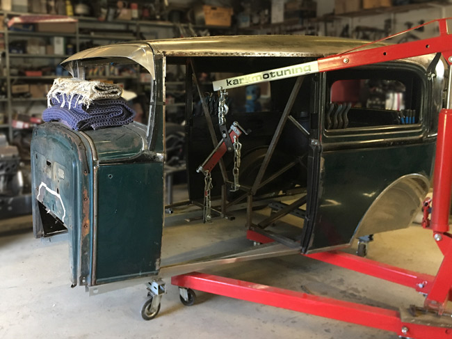
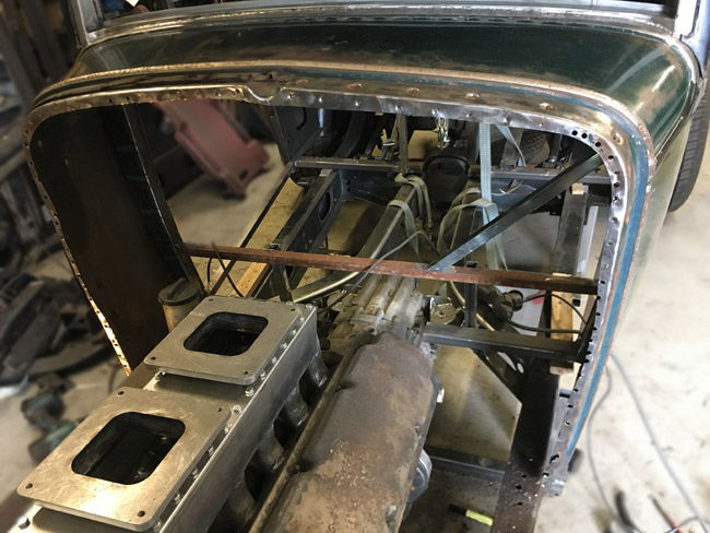
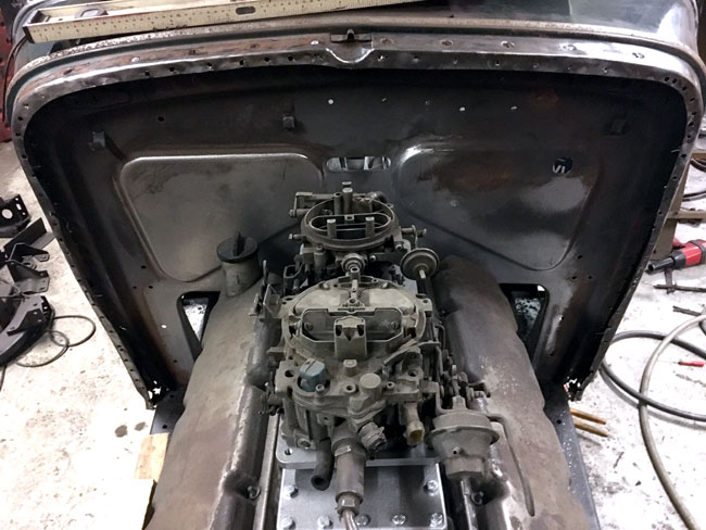
With the engine hoist and the wife lending a helping hand, the body was sat back onto the frame, where it hasn't been in almost ten months. |
|
|
|
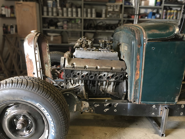
Things are looking pretty good here, although the body sits too far back, as the firewall hits the engine. The firewall has to be recessed into the cowl. |
|
The body needs to be moved a couple inches forward. |
|
|
|
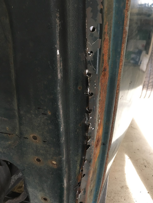
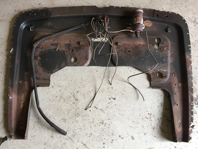
To remedy this, the firewall is going to be modified, so the numerous spot welds are drilled out with a ¼" drill bit, and hacked off with an air chisel.
|
|
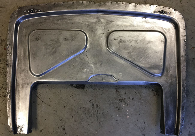
When the firewall is out, the flange with all its holes is hammered flat and the paint and rust ground off. |
|
|
|
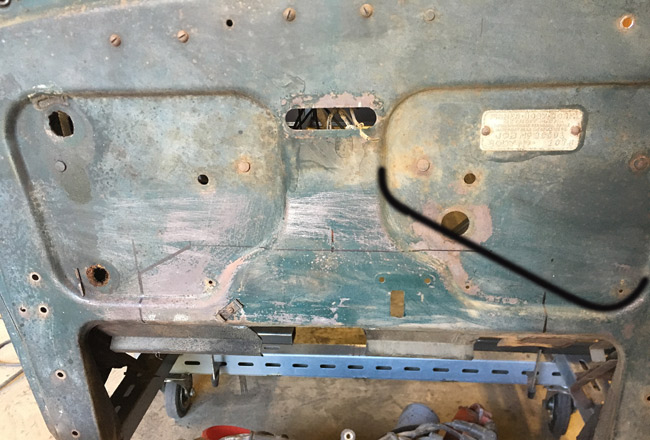
The firewal will be turned inside out to effectively move it back two inches.
|
|
To gain a bit more space, the "panels" that now protrude out of the firewall have to be modified to the shape outlined in black here. |
|
|
|
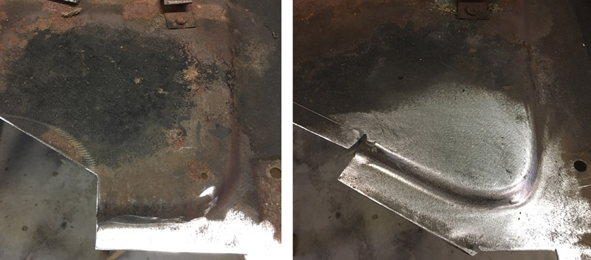
The top pic shows the first of four corners before and after modification. The bottom pic shows the second corner being done, and the completed fist panel. |
|
|
|
The result after the panels are done. |
|
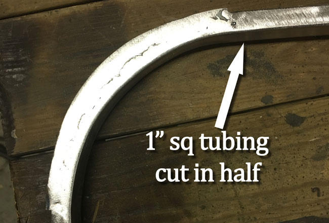
When trial fitting the firewall to the cowl, there still wasn't enough room, so a spacer from 1" square tubing was made to gain another inch. With this spacer we'll get about 3/8" of clearance between the firewall and the cylinder heads, which should suffice. The spacer is made from 1" square tubing cut in half to form a U-profile. The corners are cut down and bent, and filler pieces are made from sheet metal and welded in. |
|
|
|
It was soon discovered that he tubing cut in half wouldn't do it, so it was back to the bender and make new tubes, complete 1"x1" ones, and start over. |
|
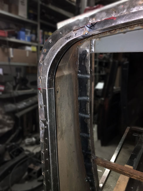
The new spacer was weded in with rosette welds through the holes drilled to get the spot welds out earlier. |
|
|
|
The firewall all ground and ready to weld to the cowl. |
|
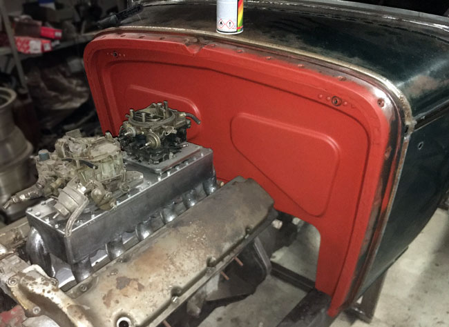
Finally the firewall is welded in and has gotten a coat of red primer. |
|
|
|
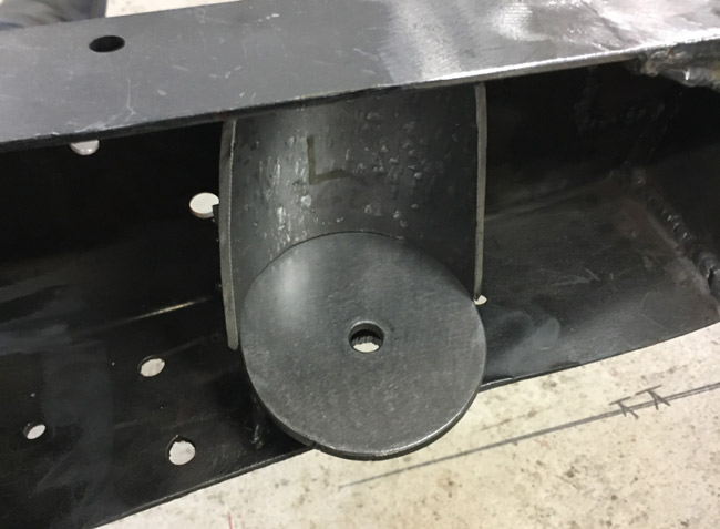
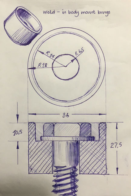
Sketch for body mounts to go inside the floor structure beams. These could have been turned on a lathe.
|
|
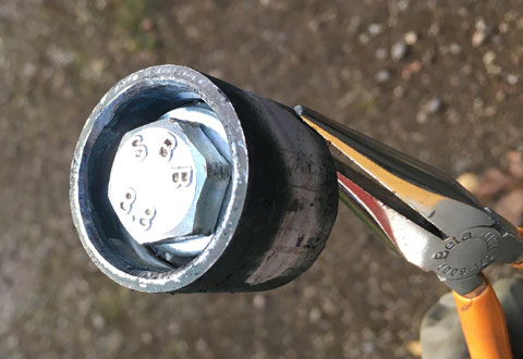
... Then it was decided to make them from a bit of pipe, a washer welded in from the underside. |
|
|
|
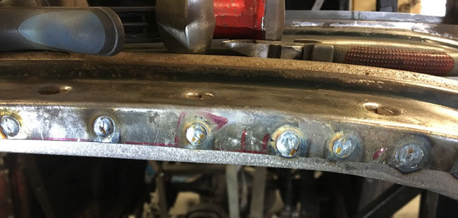
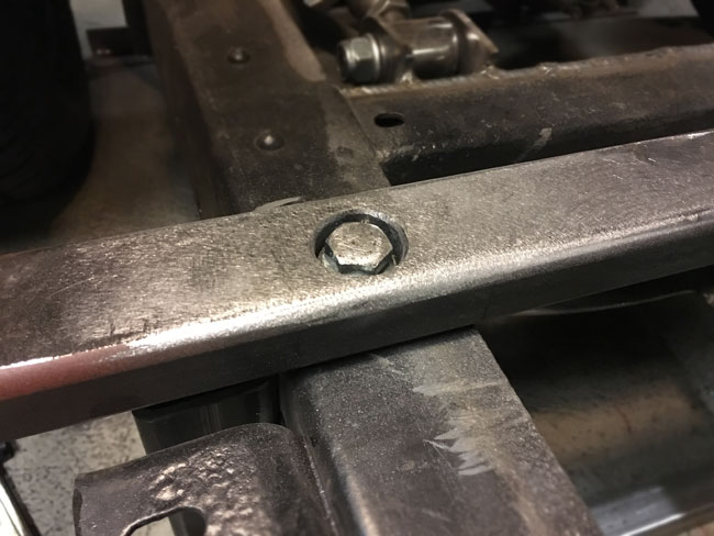
Welded into place and ground they look good, and will not protrude out of the floor.
|
|
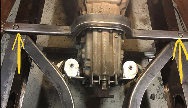
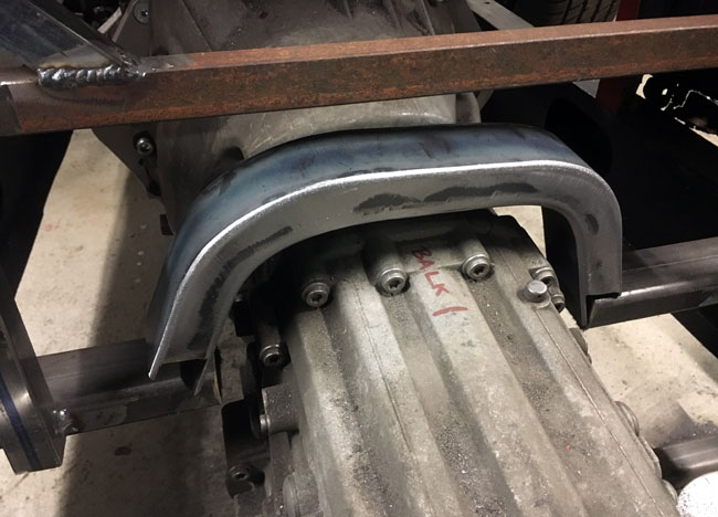
The floor structure beam that the floor will weld to, needs a stiff piece to go over the transmission.
|
|
|
|
The first floor structure beam is done. The transmission tunnel will weld to the flanges welded to the bent beam, and the yellow arrows point to the body mounts. |