|
Page 2 The project begins |
|
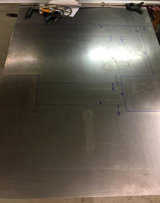
Planning for the fuel tank. Fist, where to put it. Second, how to make it fit, and still take up too much room. Third, how big it needs to be to take about 20 gallons of gas ( 80 liters), and then draw plans for it. It's a process. That done, parts were drawn onto a bigger than usual (49"x98") sheet of steel. A decision was made to cut out and make the end pieces first, which turned out to be a good idea, since the big sheet had to be adjusted slightly as the bottom of the end pieces ended up being about 5/32" oversize.
The top, front, bottom and back sides drawn out in one piece.
|
|
|
|
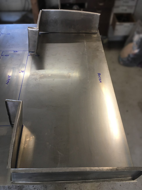
End pieces laid down on the big sheet. Good thing the side pieces were made first, as
a mistake drawing the big piece had been made.
|
|
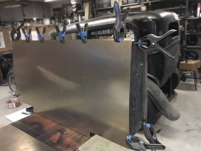
A friend's sheet metal brake was used to bring the big sheet into shape. Seen here mocked up with the end pieces. Also, a fuel tank sender, a gauge, and materials for making reinforcement plates that will go inside the tank were purchased. A local hydraulics company bent thin wall tubing for the fuel feed-, return- and breather lines. Feed will be 3/8", return and breather 5/16". |
|
|
|
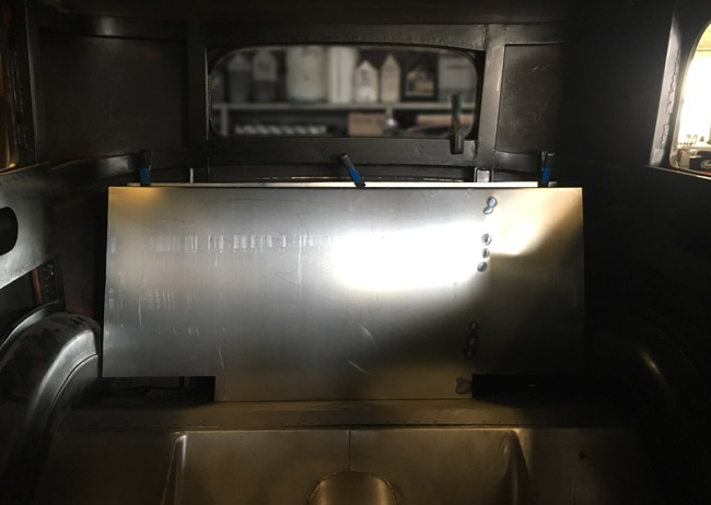
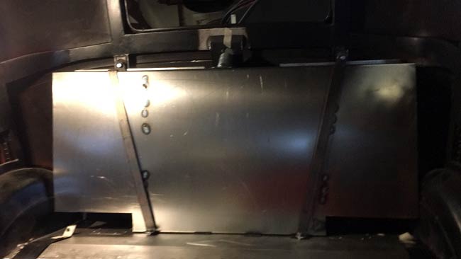
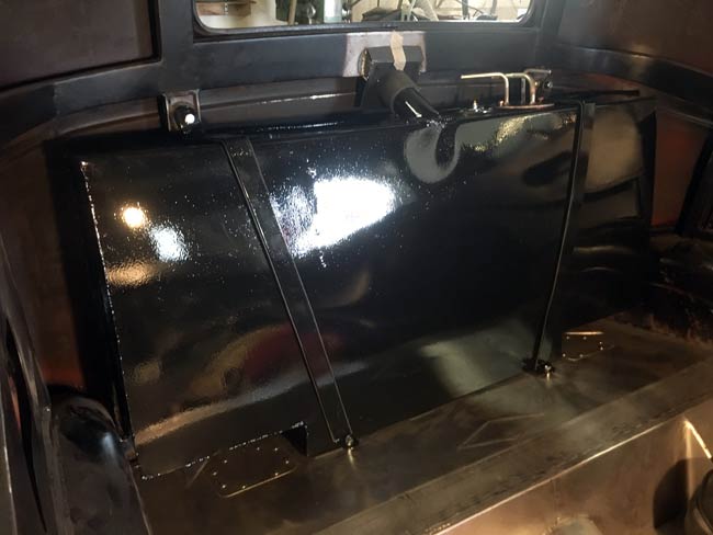
The fuel tank trial fitted to see if it fits. It does fit with only a few fractions of an inch to spare. |
|
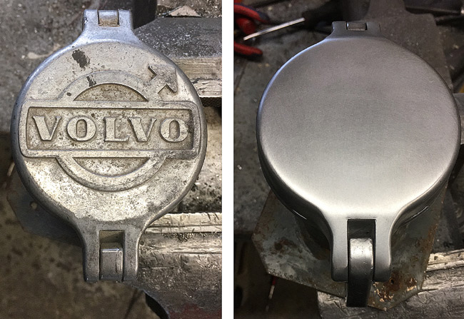
A Volvo fuel cap has been in the inventory for a few years. With the Volvo logo groud off, it looks like it might work. |
|
|
|
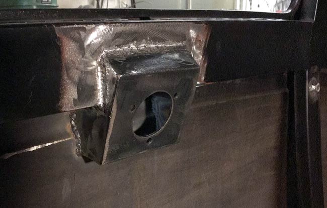
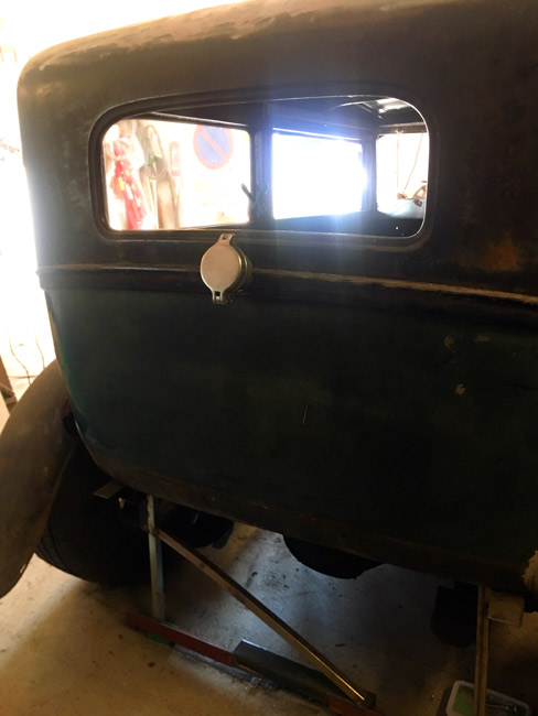
After drilling a 3" hole with a hole saw in the back of the car, the new fuel cap could be trial fitted. |
|
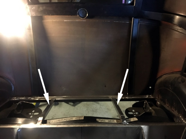
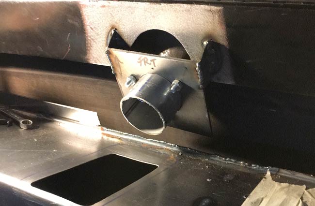
Braces (arrows) were welded to the rear body structure for the fuel tank to stand on, and to which the fuel tank hold down straps will be bolted. |
|
|
|
Finally, one of the last pieces of the new floor could be welded in. This piece of sheet metal has been waiting to be welded for six months, while the tank and structure has been planned, and other work has been done. |
|
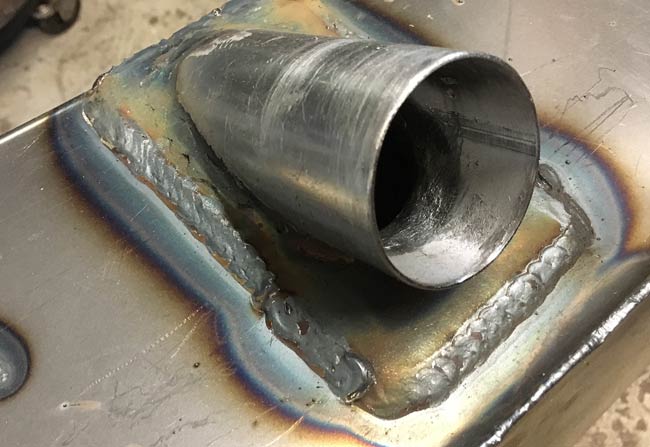
The filler neck took a whole lot of planning to figure out how to make it sturdy enough to use (you got to push the flipper latch pretty dang hard to get it to open), and in which order things had to be done to make it possible to weld everything and so that it can be disassembled afterwards. The filler tube tacked to the body here, and cut off where a piece of rubber tubing will connect it to the fuel tank. |
|
|
|
Hold down straps made from 1/8" x 1-1/4" flat bar.
|
|
The other half of the filler neck baked onto the tank pretty hot with the MIG. |
|
|
|
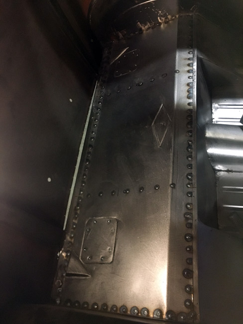
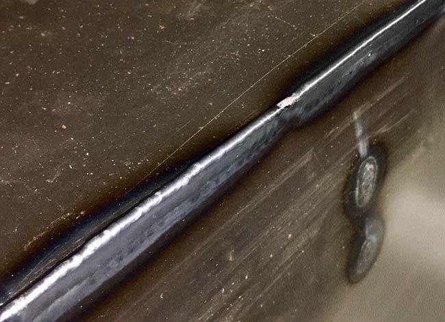
Flanges around the whole tank makes it pretty easy to just fuse the parts together with
the TIG torch.
|
|
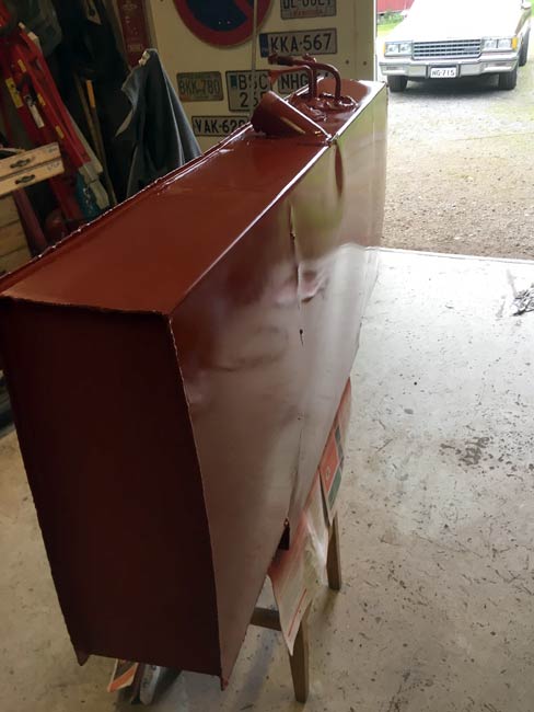
The fuel tank is done, but after leak testing it with dish soap and water, it started rusting. It was ground with 180 grit on the D/A and sprayed with red primer. |
|
|
|
Tank painted with industrial 2K paint, final trial fitted with straps and rubber mounting hardware.
|
|
welded The gas filler neck mount was welded tight against the body. The idea being that when fueling, any spilled gas doesn't smell inside the car. |
|