|
Page 2 The project begins |
|
Plans call for Air-Maze stickers on the air filters. The top one here is adjusted to look more American, whereas the bottom counterpart is the original brittish version found on the oil bath filter housings. |
|
|
|
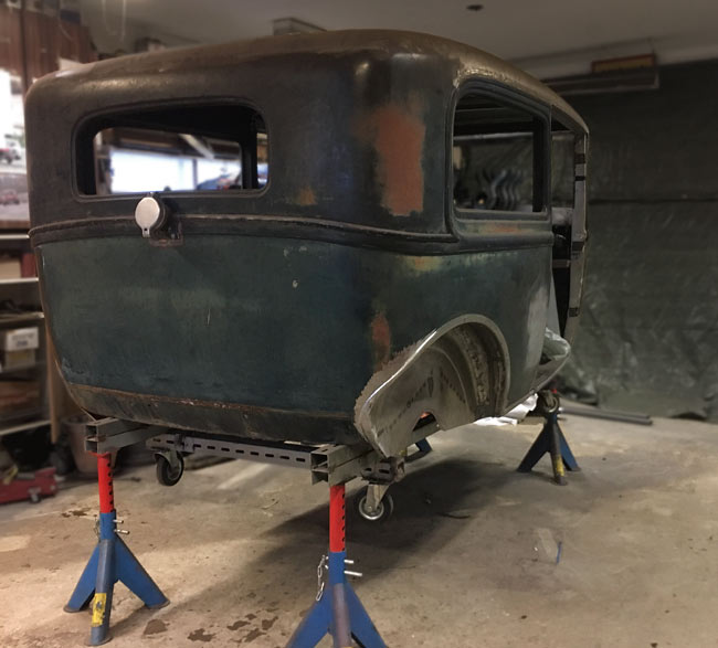
The body was jacked up onjackstands to make room for work from the underside. Some welding had been left undone before, because the frame was still bolted to the floor. |
|
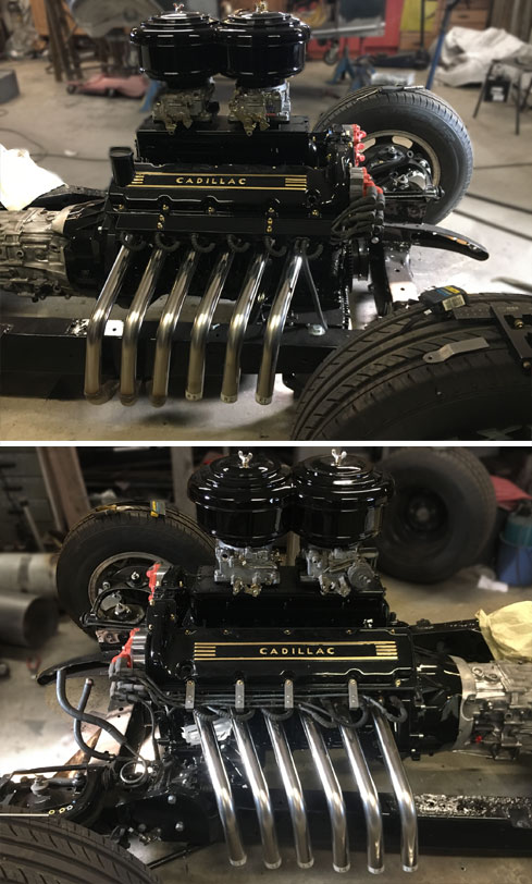
A few days went into designing, shopping for materials and making an ignition wire holdup thing. The ignition wires need to be held with something, since they run above the exhaust headers. This design utilizes the original loom inside a rectangular pipe. When I got it in place, I thought it looked awful big and didn't like it. Even painted and decorated with brass acorn nuts, it looks too bulky, so a more simple approach with exposed wires was tried which was deemed to look better |
|
|
|
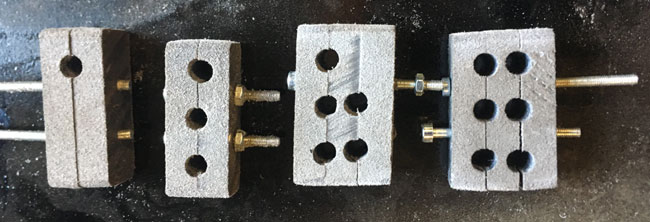
These things were from nylon and they hold the ignition wires nicely and scurely. They
are held together with M3 screws and nuts, about 5-40 size. The plastic looks
very light gray here, because the parts are sanded with coarse grit, but it's
actually black nylon.
|
|
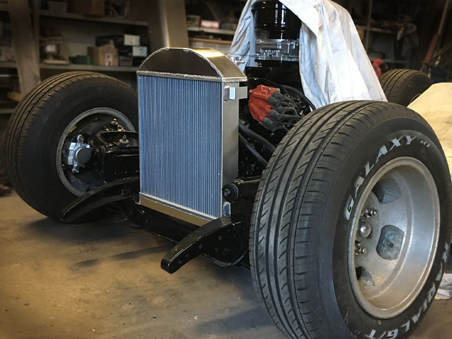
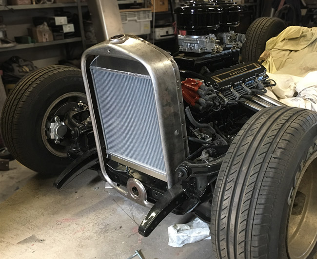
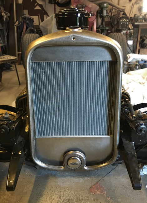
We got a nice size parcel, which contained a radiator. It was tried it in its new place today. It's for a model A Ford and fits fairly well in the Buick grille shell. |
|
This was going to be a large patch, here's how it went:
Templates were made from wood and wood screws, to have something to
check the shape of the sheet against while it was rolled it in the English wheel.
Back at home the new sheet was centered and levelled and fastened with four
sheet metal screws in lieu of clecos.
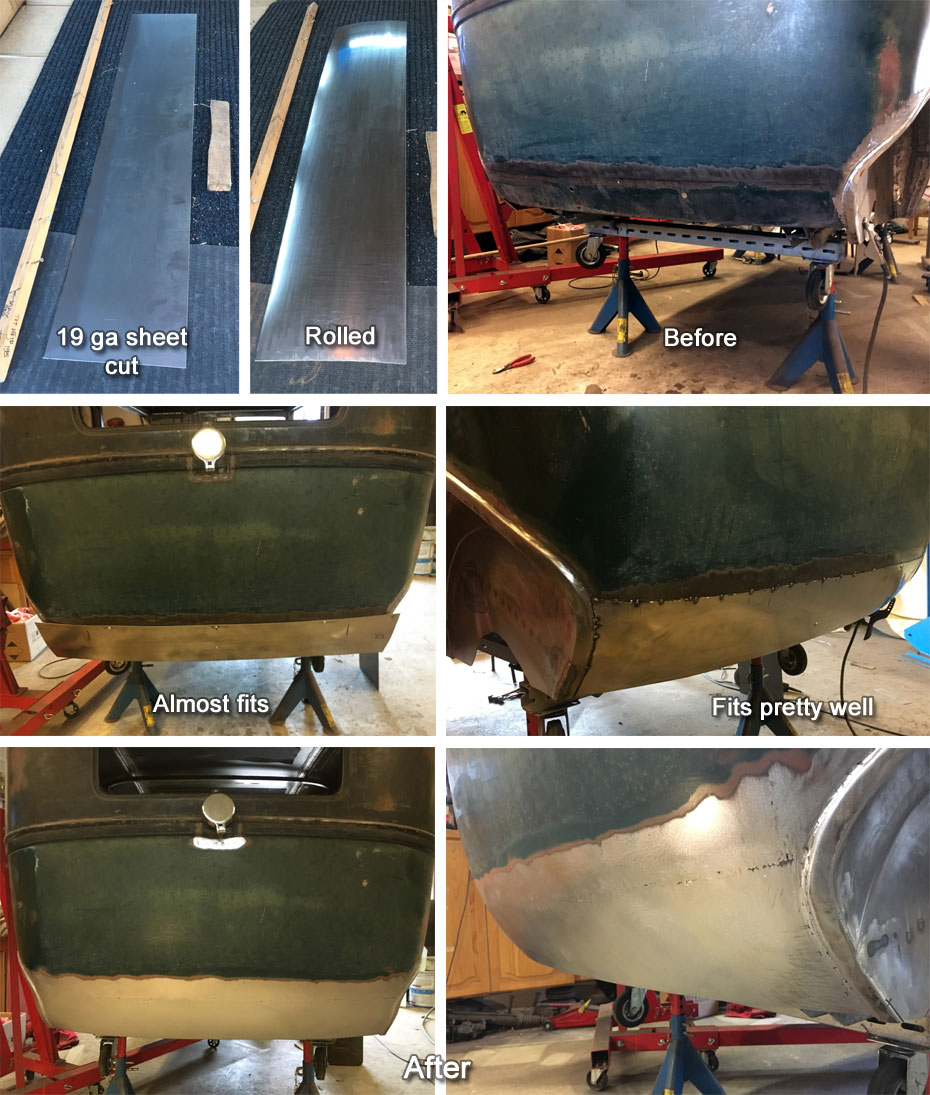
Then a lot of shrinking in the deep throat schrinker-stretcher was done. When the
shape looked okay, A 3/4" flange was made using a tipping die in the bead roller,
then the flange was shrunk with the shrinker-stretcher to get back to the right shape.
|
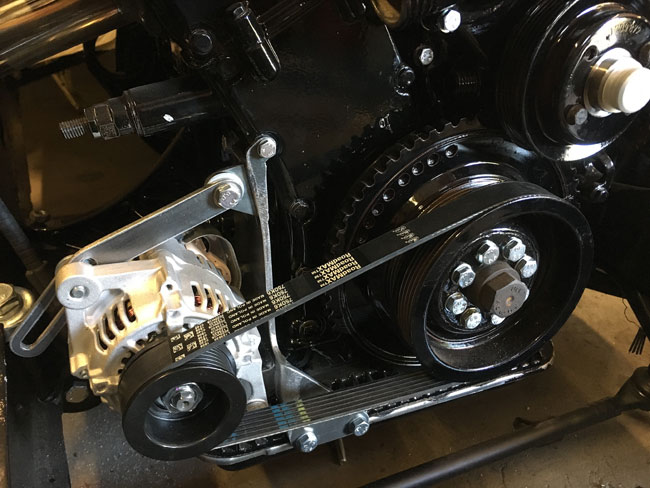
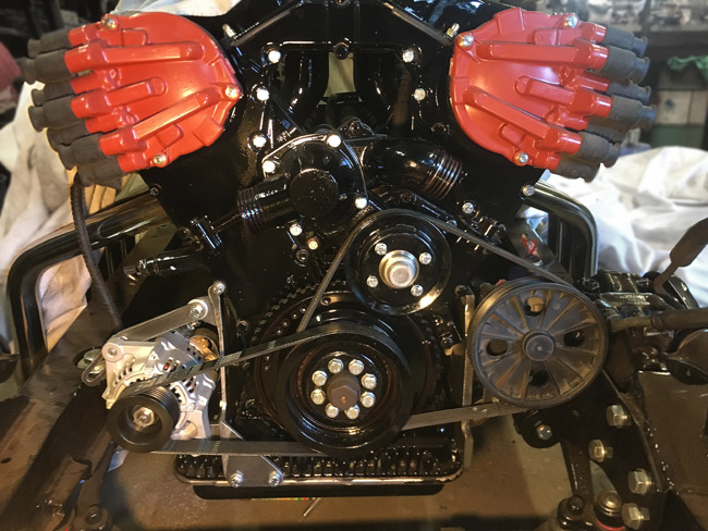
This is a 40 Ampere alternator, meant for a Kubota engine. The plans originally called for V-belts, but I thought the better of it, this project witll never be done if we're to alter every detail, so instead a new wide belt pulley was purchased and a 15-17 mm bushing to make it fit the axle. Of course the pulley was too thick for the short axle, so it had to be turned down about three thirtyseconds on my uncle's lathe for the nut to have enough threads. It's never as easy as it looks. |
|
|
|
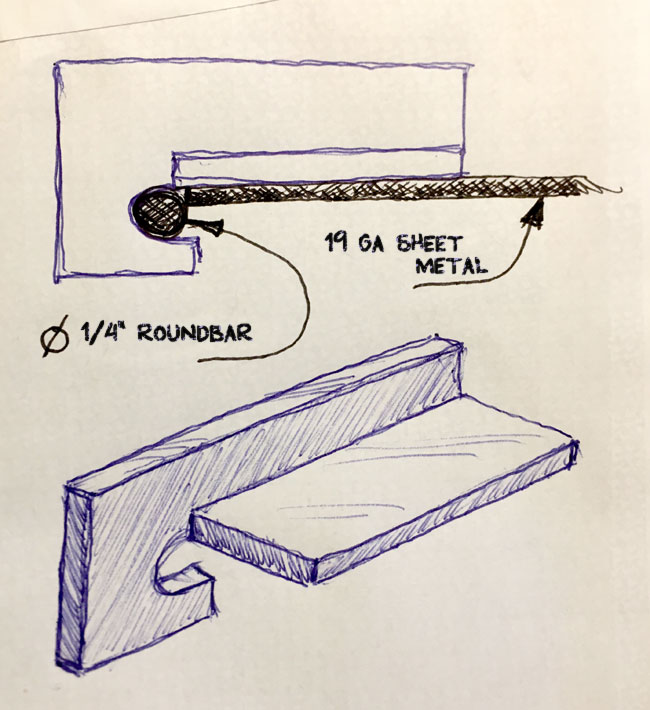
Some clamping tools to get 1/4" round bar welded to the wheel tub edges were sketched up. |
|
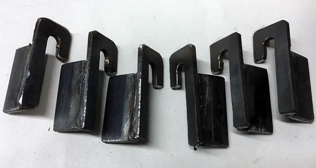
Six of them were made, three and three, mirrored. Six turned out to be enough or this kind of job.
|
|
|
|
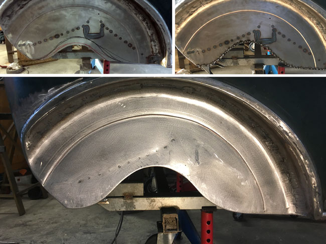
Here's before, when tacked, and after. The edge looks much more like it belongs now, and the clamping tools worked great combined with vice grips. |
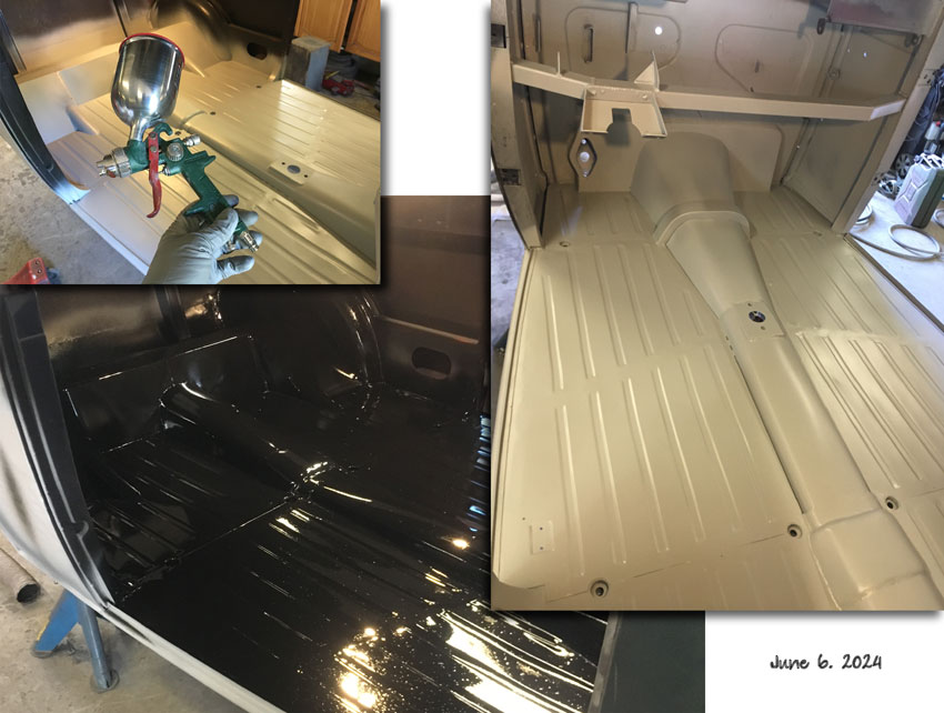
The floor was sanded, top and bottom, and scuffed with 180 grit on the orbital sander,
shifting to hand sanding where the machine wouldn't go. Then washed with thinner.
The floor and the firewall with grey epoxy primer. Day 2, the top side of the floor was
epoxied too. In the evening all of it was spayed with 2K black industrial paint.
|
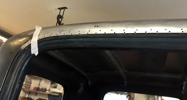
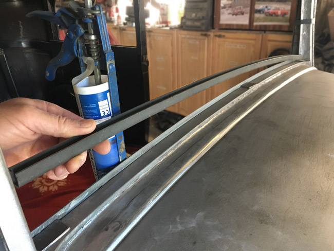
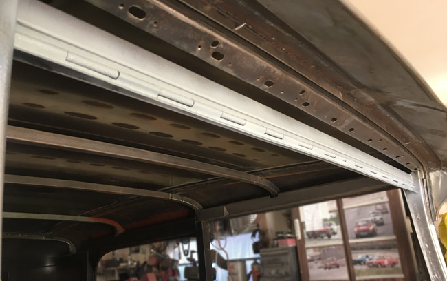
The drip rails were in the car when it was bought, but they were a mess, and deemed unusable. |
|
|
|
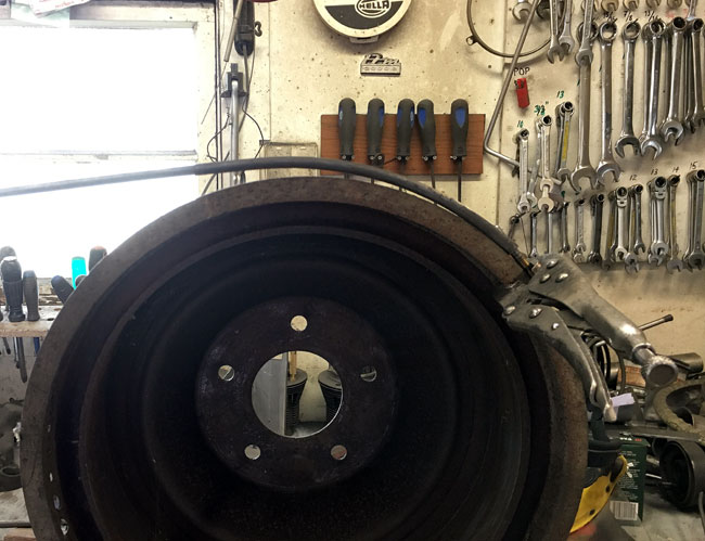
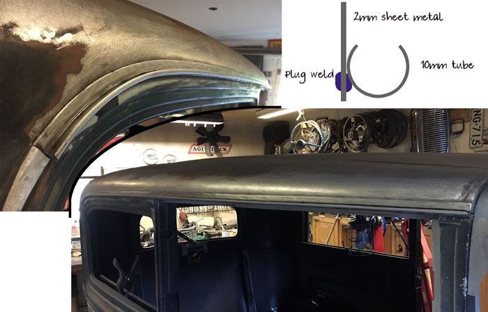
The old drip rail was about the size of a 10mm diameter tube (about 3/8"), which was used for this project. About a quarter of the tube was cut away along its lenght, two meters or 80" of pipe on each side. Then the pipe was bent over a large Pontiac brake drum that happened to be of the right diameter. |
|
Welding the tube to the sheet metal strips was tricky, as it effectively had to be done from the back side. |
|
|
|
Some flaked chrome trim and the cowl lights had been removed from the cowl, resulting in 22 unsightly holes that had to be welded shut |
|
Time to make the windshield
frame.
|
|
|
|
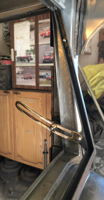
A couple hood hinges from a thirties car were used to make the wind shield top hinge. |
|
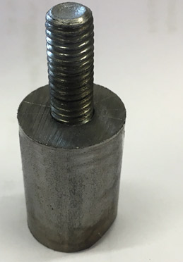
For opening mechanism some 3/4" round bar was used. A through hole was drilled and a sawn off bolt was welded to the other end of the hole, so there's something to screw the windshield opener to.
|
|
|
|
After a bunch of measuring and finally welding, the windshield frame with its opener mechanisms is done. |
|
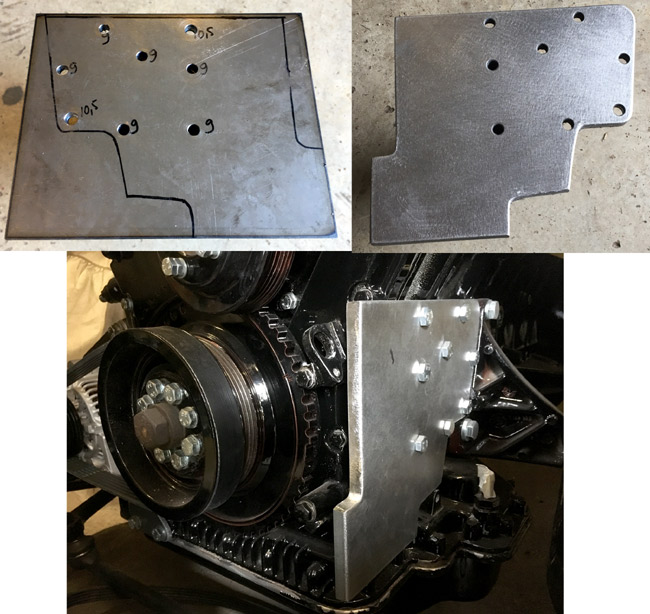
Back to the accessory belts. This engine has a remote oil filter, and becasue thatwon't fit in among the headers and narrow chassis, that one still needs figuring out. In any case, the oil filter connections will be in the same 10 mm (about 3/8") thick piece of plate asr the pump mount here. More on that later on. Lots of grinding and drilling to make this part. |
|
|
|
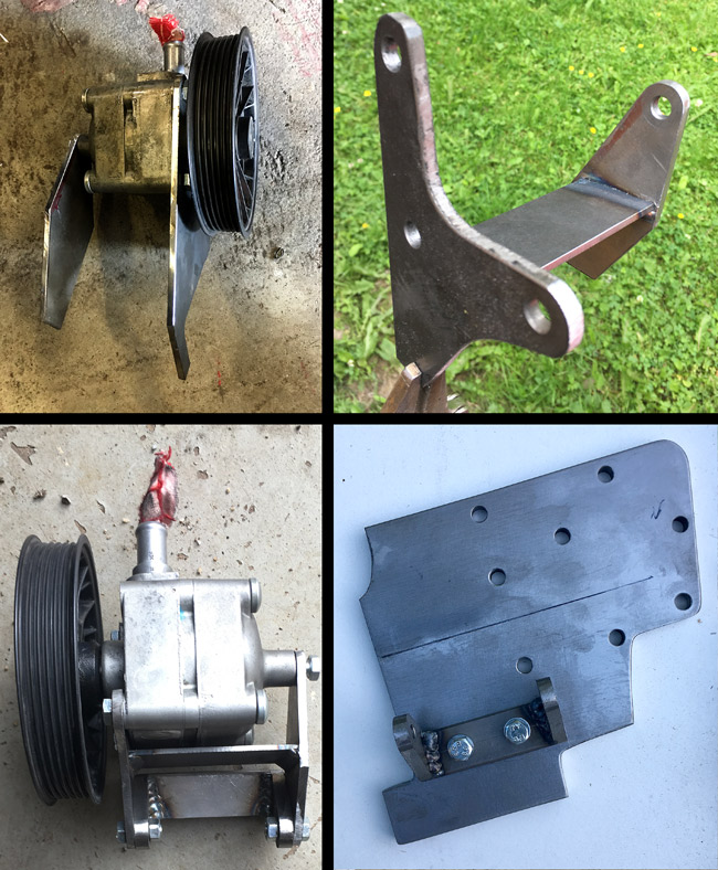
The plate with all its holes fit first try. Unbelievable. Usually it's hard to get more than two holes to fit. Then the pump mount was made. It will pivot on two bolts, to assure the belt runs straight. Also a mount for the mount was made from 8mm (5/16") plate. The hard part was to get the little mount in the right position, so a buddy gave a hand, holding the pump in the right position while I scribed. All parts back on the work bench, holes were drilled and tapped, and the parts were bolted together. |
|
Lo and behold, it came out spot on! First try. This never
happens. |
|
|
|
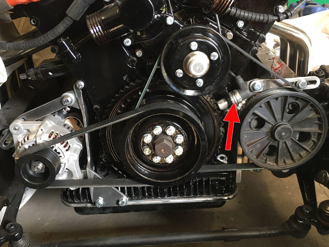
The belt tensioner for the power steering pump is done. Also the crank sensor (arrow) is in place, and things made so it can be replaced without removing more than one bolt. |
|
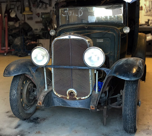
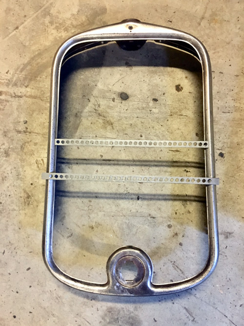
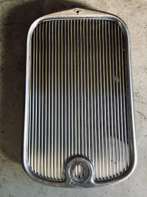
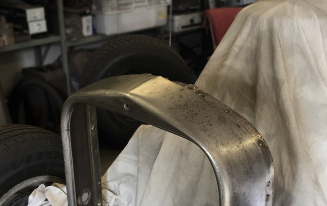
Next up is the grille. The shape of the grille shell is nice, no need to alter that, but the original grille is not a favorite, it's just a stamped sheet, so it was decided early on to make a tube grille. |
|
|
|
For tubing chromed copper 10 mm diameter waterpipe is used.
|
|
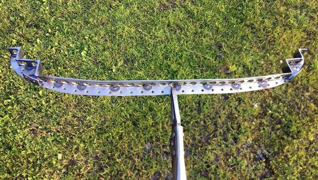
The botom matrix here. It took some figuring out to get a nice fit without it showing from the front of the grille, and to get each of the tubes fastened so the whole thing won't rattle. A box of very small sheet metal screws is used to get it all mounted. |
|
|
|
All the parts and tubes trial fitted. It looks okay, the spacing of the tubes follow the shape of the grille fairly well. The crank hole will get a filler piece, it doesn't look right as you can see the tubes going past it. |
|
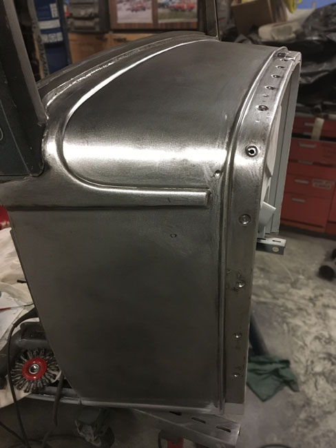
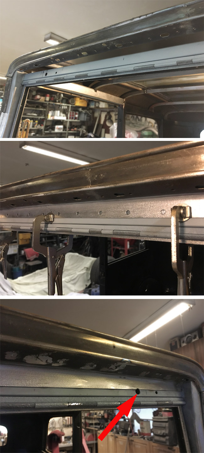
A small piece of sheet metal was missing between the windsheild opening and the roof.
The new piece is lined up with vice grips, ready for plugwelding.
The welds were ground down. Some welding still to do on the old "forehead" of the roof.
|
|
|
|
The new aluminum radiator was mounted to the shell and as luck would have it, the mounting tabs for this radiator, meant for model A Fords coincided with some convinently placed original holes in the grille shell. |
|
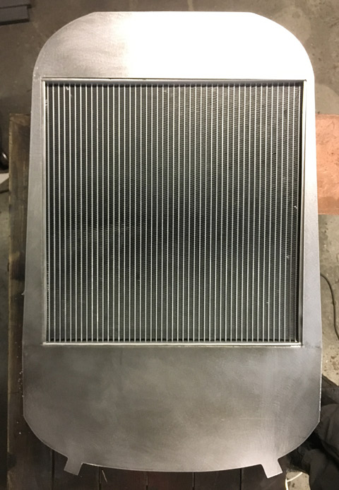
The fact that you can see through the grille around the radiator isn't a good look, so a shroud was fabricated from 19 ga (1mm) sheet metal. |
|
|
|
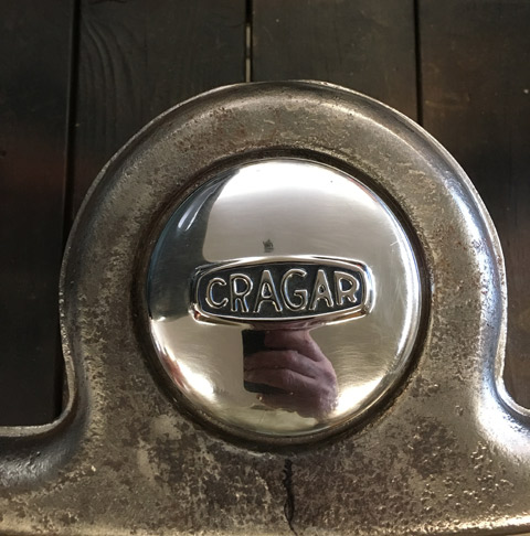
An own version of a crank hole filler piece was made from a cut down Cragar wheel center cap that had warmed a shelf for far too long. |
|
The radiator and grille shell done now, pending paint and assembly with the tube grille. Radiator and shroud will be flat black, grille shell gloss black and the tube grille chrome. |
|
|
|
The radiator cap hole was deleted, and a piece of sheetmetal with a small peak made on the bead roller was welded in instead. |

