Modifying the oil pan and propeller
axle, turbo lubrication etc.
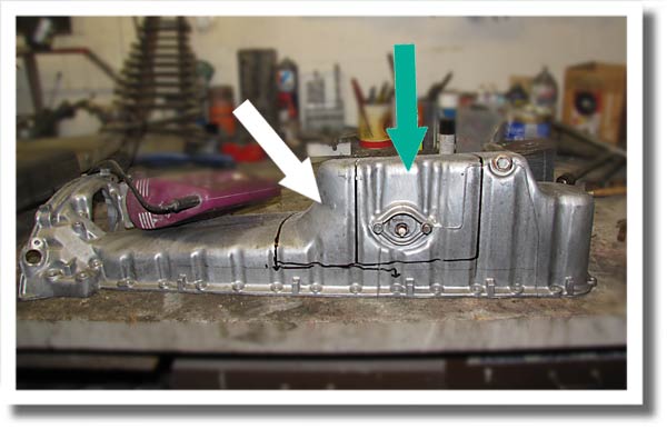 |
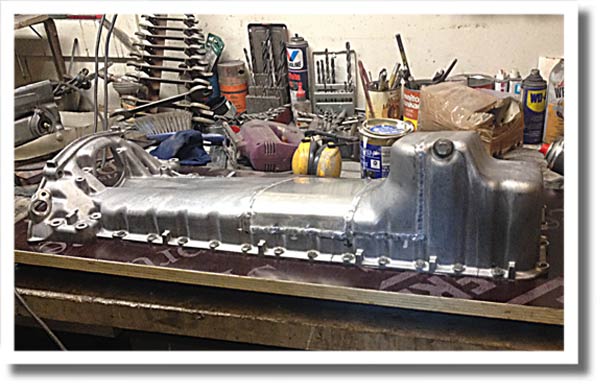
This is the oil pan upside down on the work bench. It's going to get cut along some of these black lines. |
|
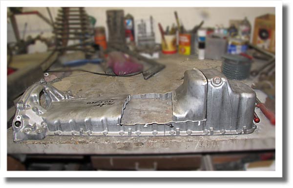
Here it's obvious how much smaller the oil pan will be, and from now on less than six quarts of oil will go in it. |
 |
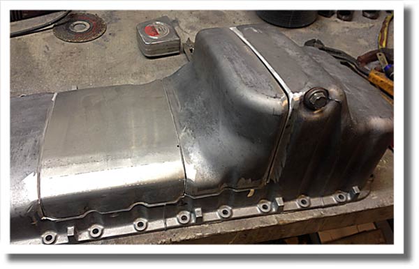 |
Some cutting and hammering, bending and grinding later the hole is filled with a piece of sheet aluminum. |
|
After contact with the heli arc welder at Kims body shop, the oil pan looks like it would once again be up for its task. |
 |
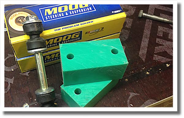 |
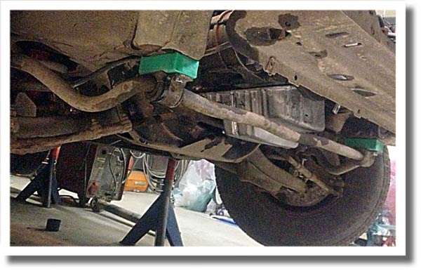
New sway bar end links and bushings, along with 2" sway bar spacers, to move the sway bar down, away from the Mercedes oil pan. |
|
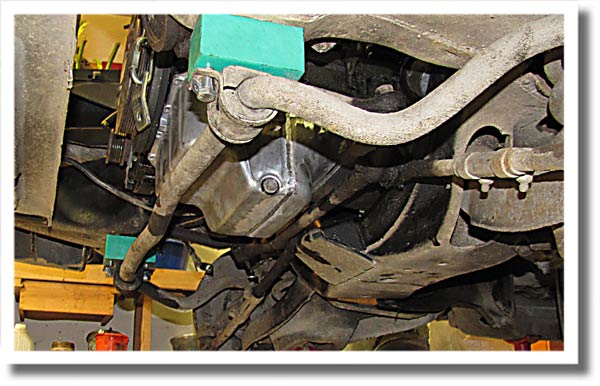
Spacers mounted between the frame and the sway bar bushings. |
 |
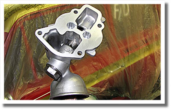 |
The rear part of the oil pump, which was taken off a four cylinder engine had been used with very dirty oil and looked awfully worn. |
|
The sway bar spacers were cut a bit smaller and here are cinched snug. The end links were tightened too. The clearance between the sway bar and oil pan is just over a ½", hopefully it's adequate |
 |
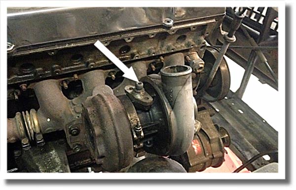 |
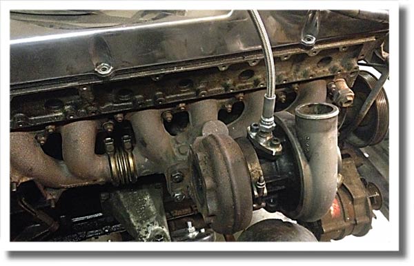
The compressor side of the turbo can be rotated to fit, and has been adjusted in this pic. |
|
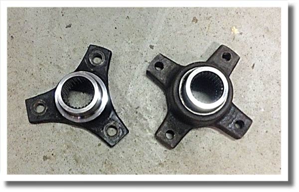
Mercedes transmissions don't have slip yokes like the Turbo Hydramatics. Instead they have a rubber flex joint which bolts to the yoke in the rear of the tranny with three of four bolts. Of course the Sprinter van transmission had the sturdier version, and the prop shaft was the smaller three bolt version.Luckily the splines are the same, as is the outer diameter for the seal, so the yokes are easy to swap even from a manual to an automatic. |
 |
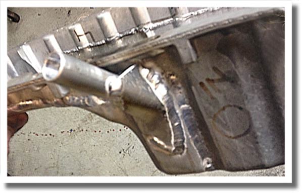 |
As oil goes into the turbo charger, it also needs to get out. As a return line is needed, a hole was drilled in the side of the oil pan and a short piece of 5 ⁄ 8" outer diameter (16 mm) tubing was welded to it. A reinforcing piece of sheet aluminum was welded to the tube and pan to prevent cracks later. |
|
Here the oil pan is bolted to the the engine, which is hoisted back into the car. |
 |
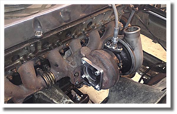 |
Good friend Leif made this exhaust flange, so now it's just a matter of welding together a new exhaust system. |
|
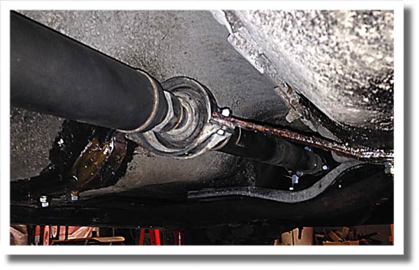
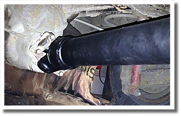
After mounting a new rear seal and the three bolt yoke, the prop axle could be mounted. The Benz prop axle is different than your usual GM axle in that it does have a slip joint aft of a prop shaft bearing. As there's no slip joint at the rear of the transmission said bearing has to be used. |
 |
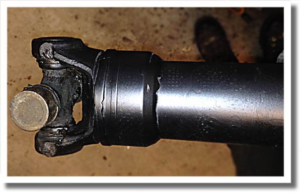 |
The rear end of the rear part of the prop axle looks like this after shortening and mating with the Chevrolet yoke. |
|
A couple of days later the newly shortened prop axle is mounted, and now it fits perfectly. |
 |
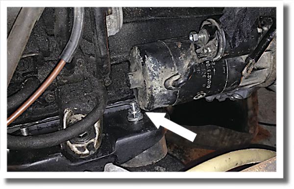 |
The starter is mounted too. The clearance between the starter and the engine mount is .025" (0,6 mm). A close call. |
|
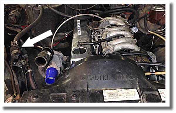
Some work has been done in the engine compartment. |
 |
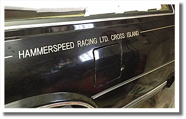 |
The stickers came! Gold on black. Gotta have some fun too. |
Go to NEXT page
THE BEGINNING THE DETAILS ADJUSTMENTS
Back to KARKMOTUNING main page